Setup Stands Part 2 – Roll Out!

Roll off pads are very useful for setup, allowing a place to make alignment changes, to zero the scales, and to allow the tire to roll to undo any bind that setting changes may have introduced. They are also the thing that adds a TON of cost to the commercial setup stand options.

Since I’m fully committed at this point, might as well go big.

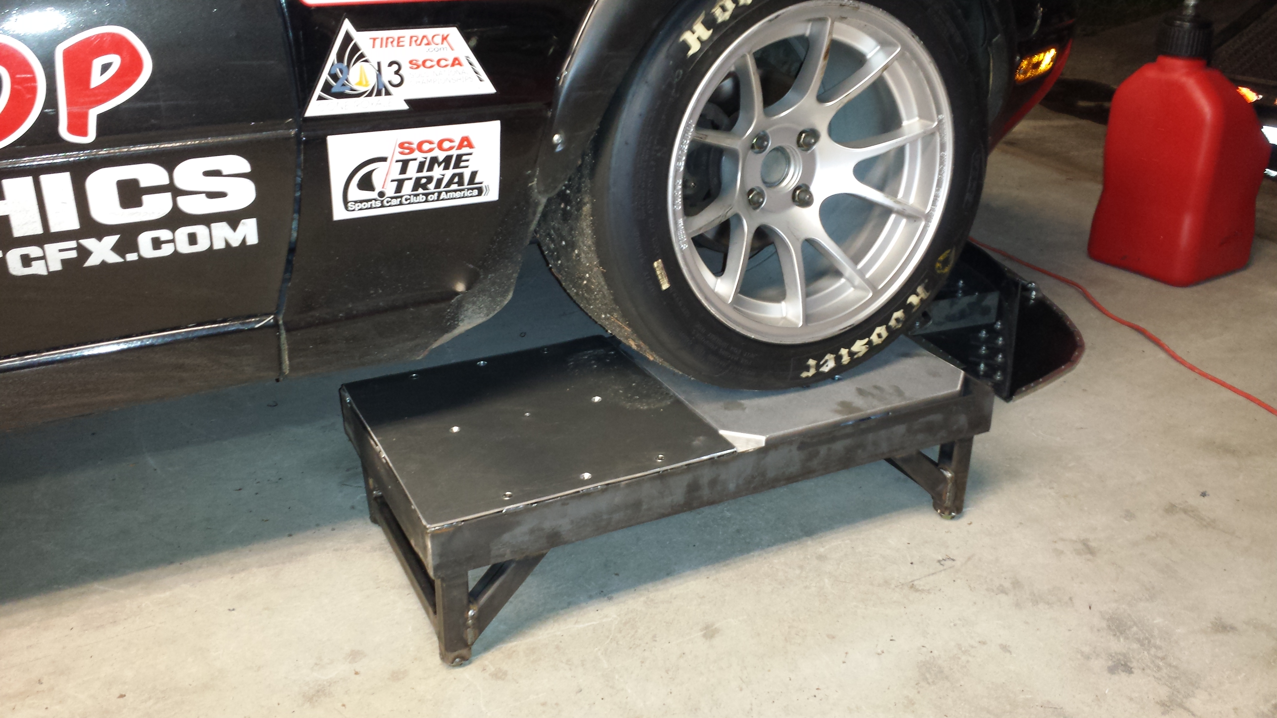
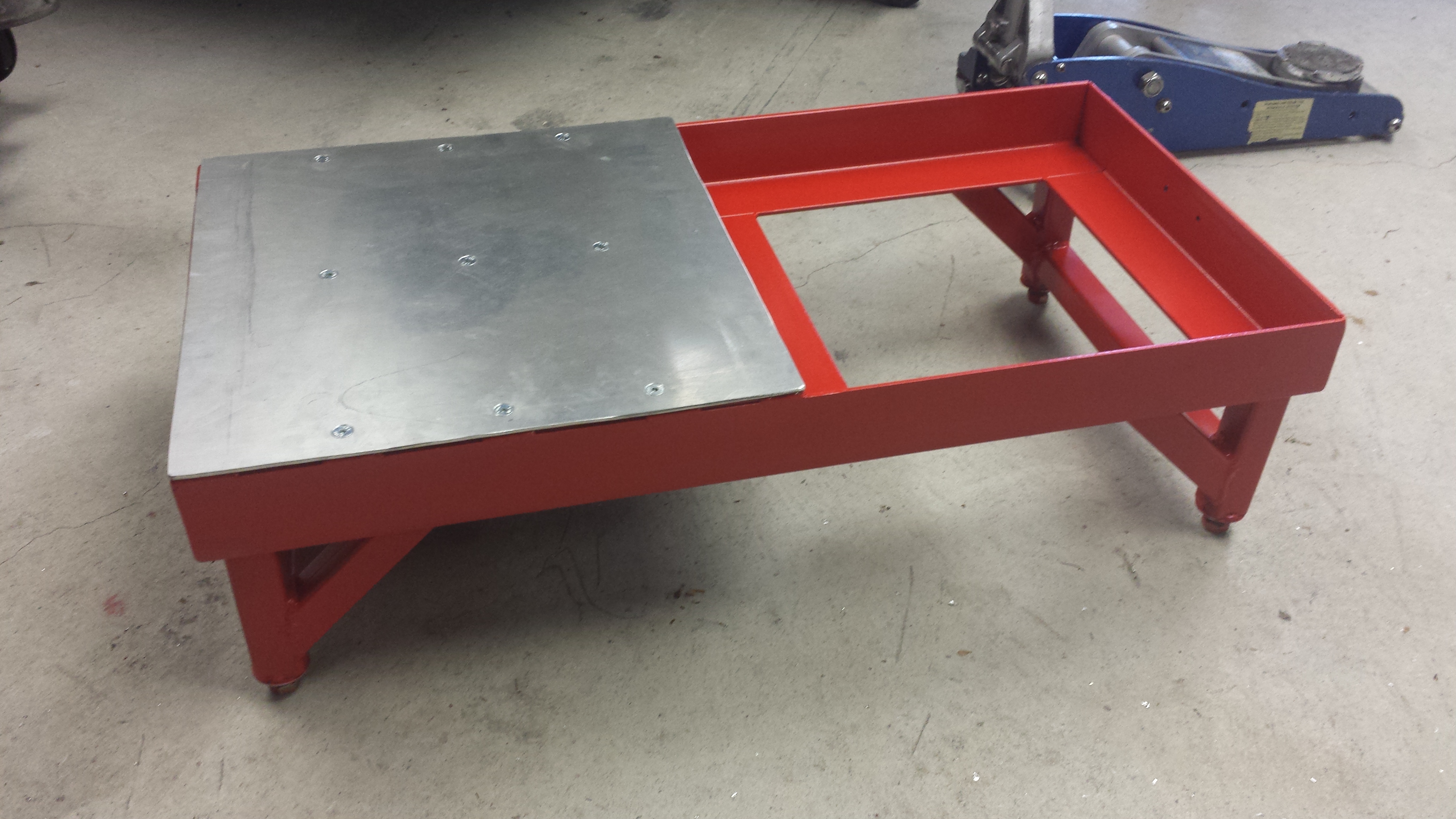
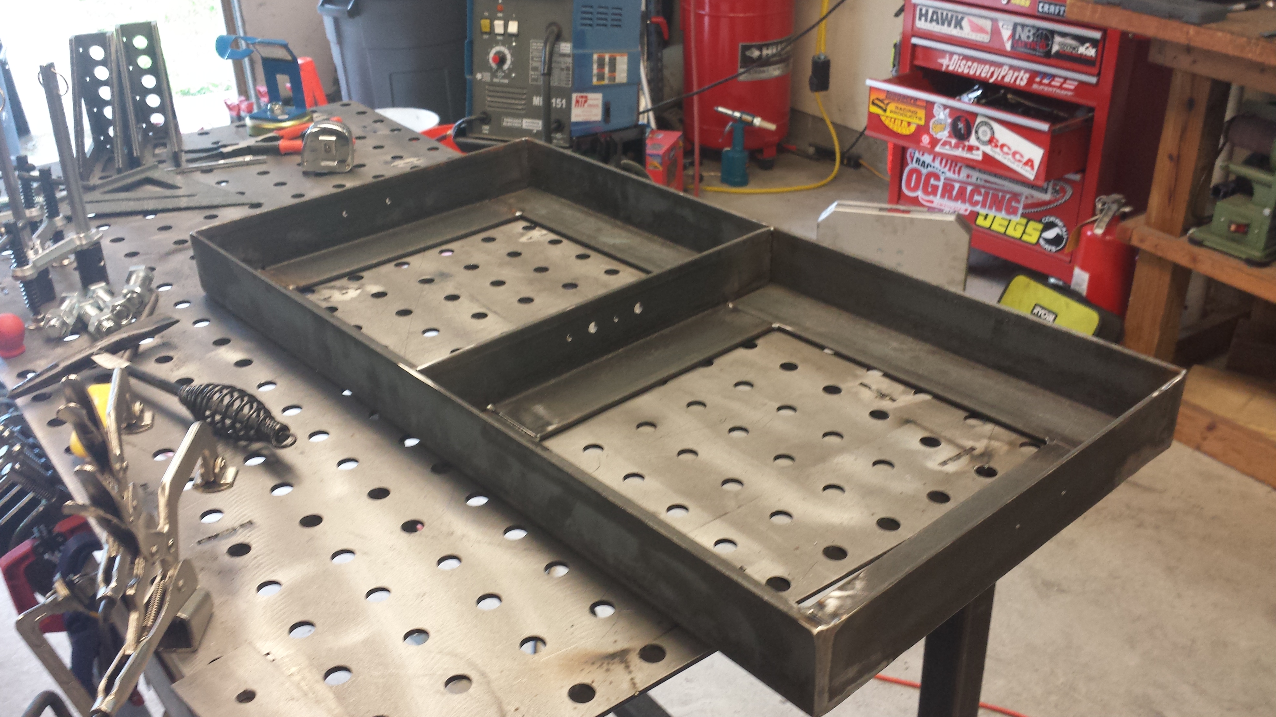
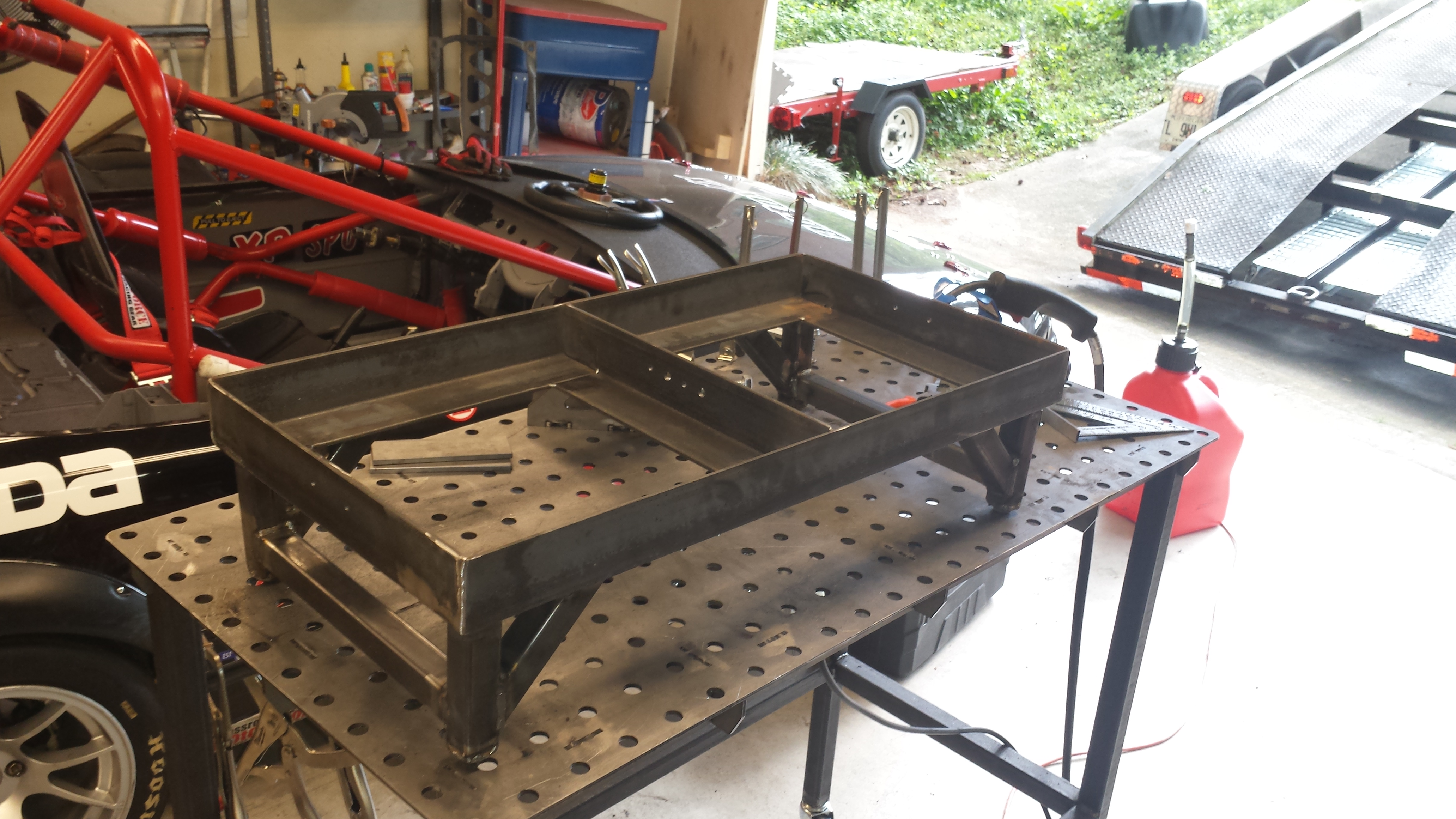
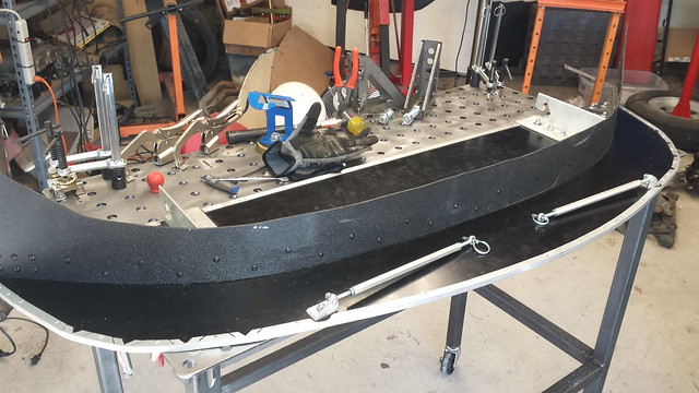
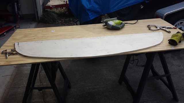
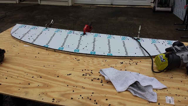
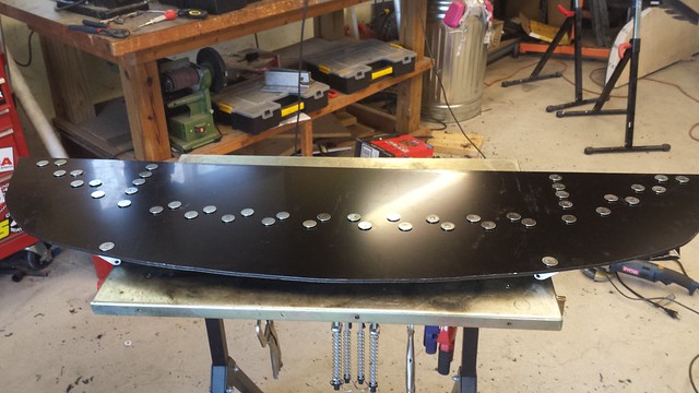
The pad itself will be a piece of 1/8″ aluminum sheet, supported on both sides and in the middle.

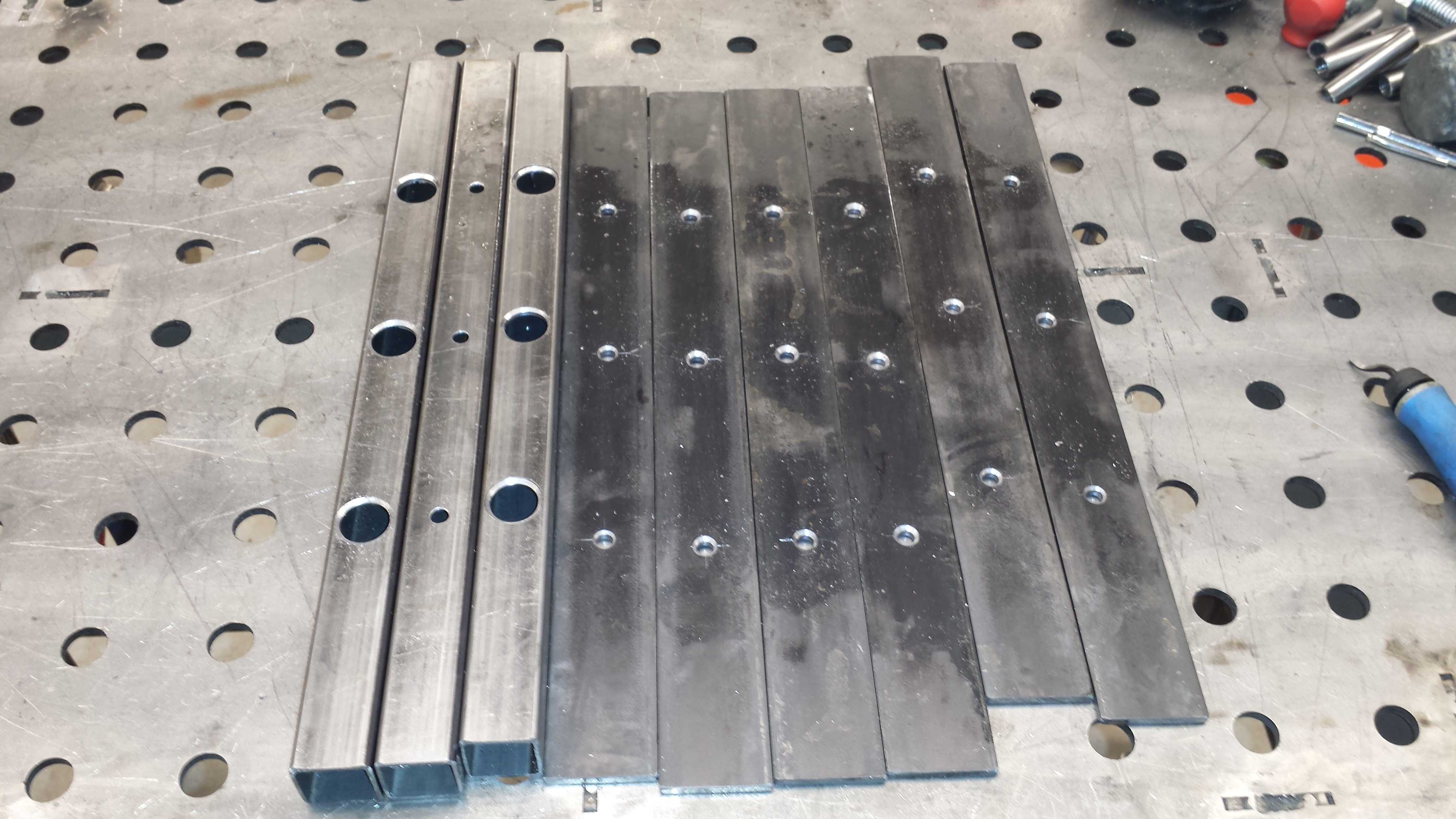
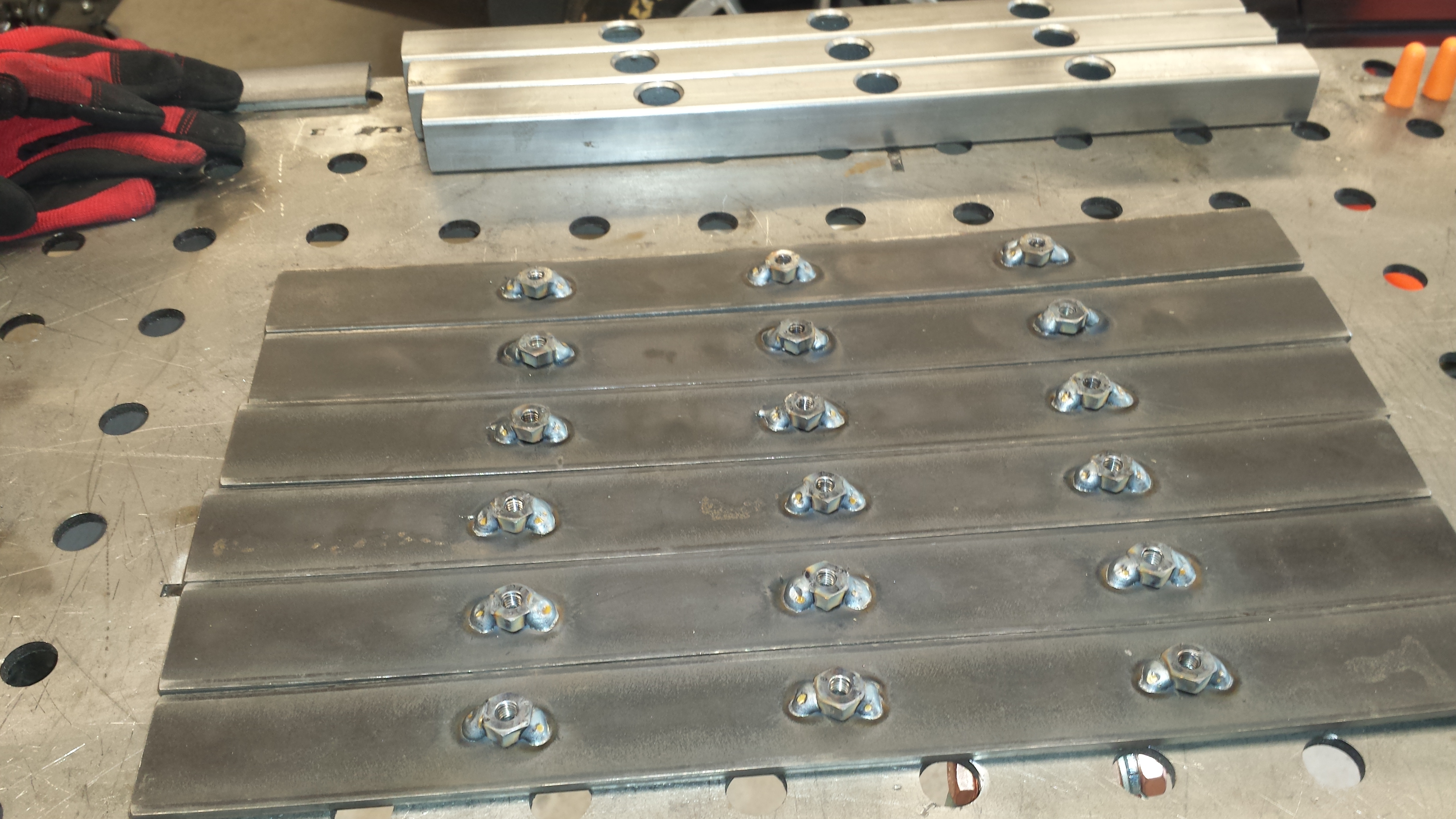
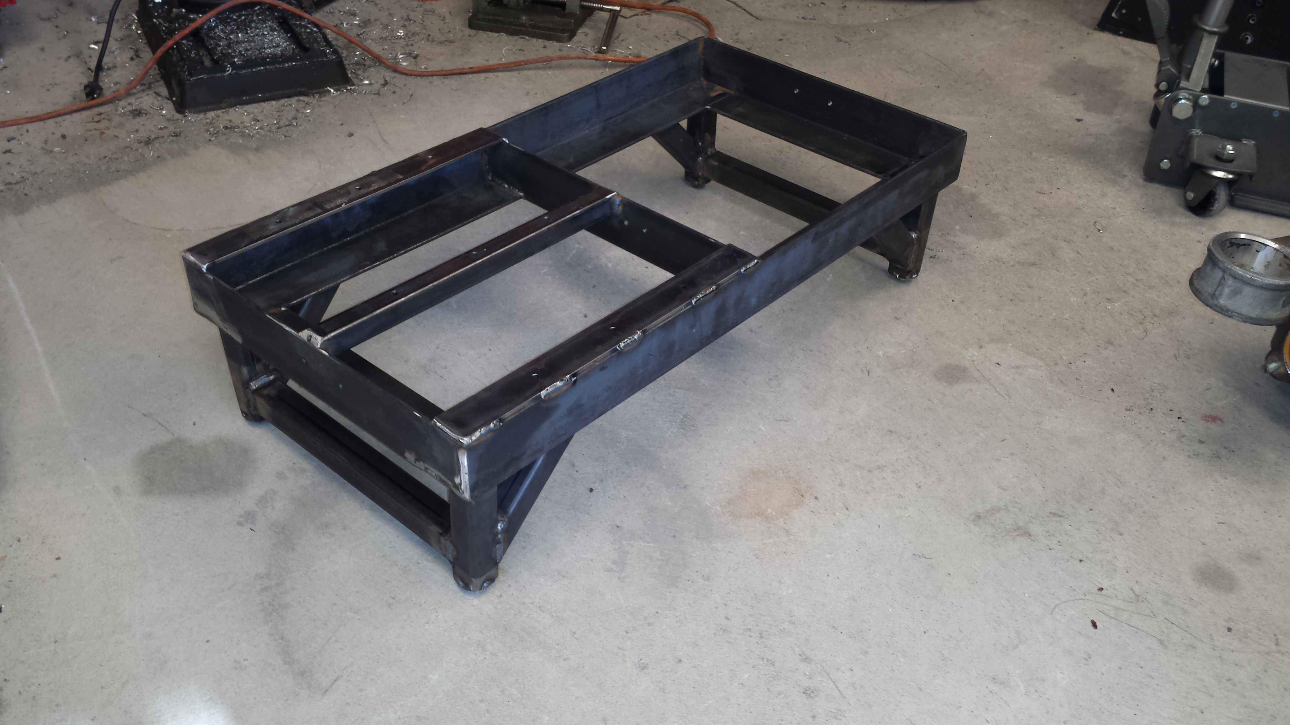
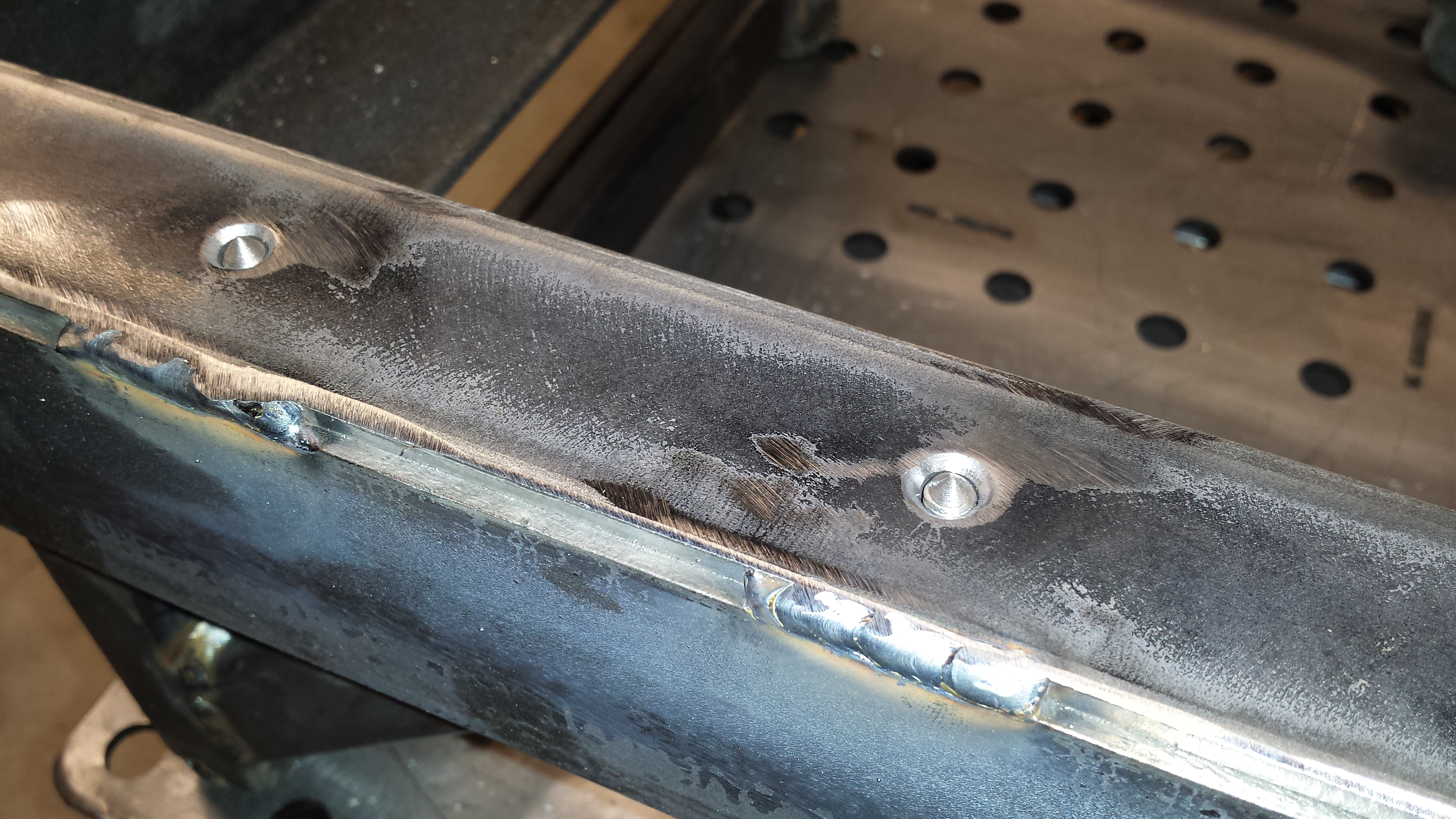
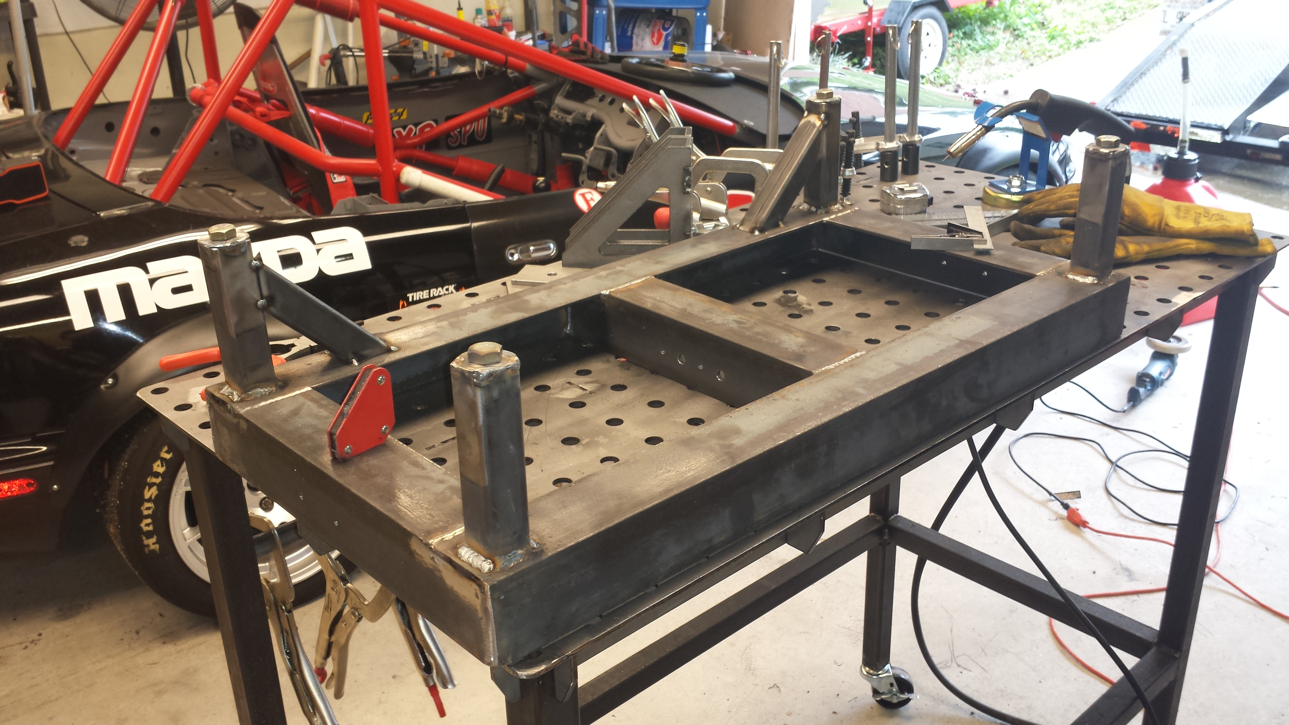
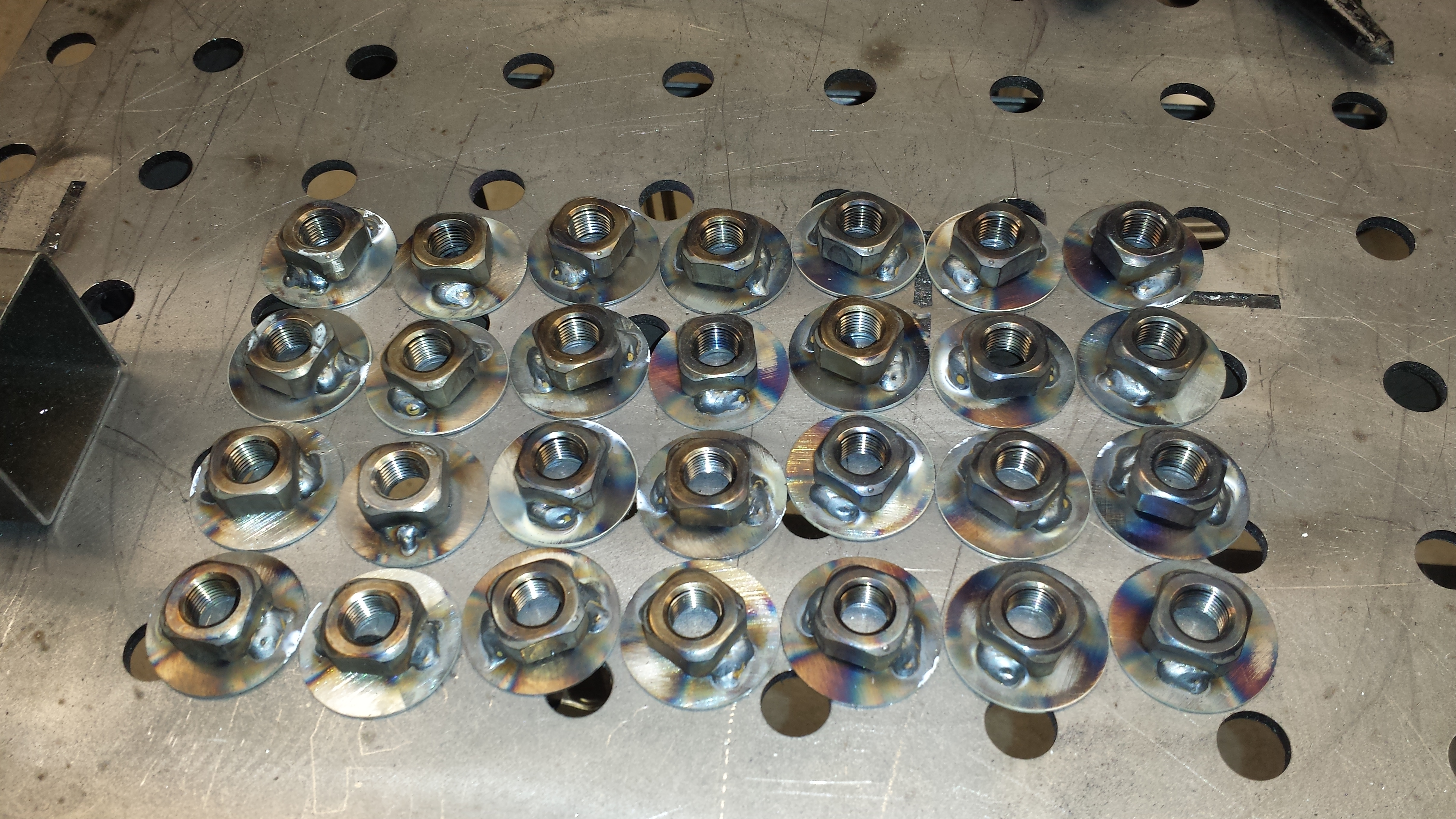
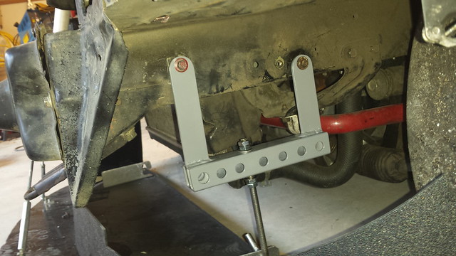
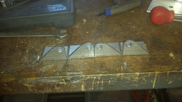
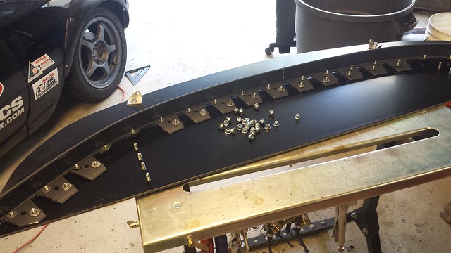
The side supports are made of 3/16″ steel bar with 3 holes per side drilled and a nut welded to the back side on each to secure the plate. The bars are supported on 3 sides, sitting on the frame on the short sides and 1 long side. Those bars on top of the frame puts the floor just a shade lower than the scale pads, allowing space for some thin grease plates to do alignments.

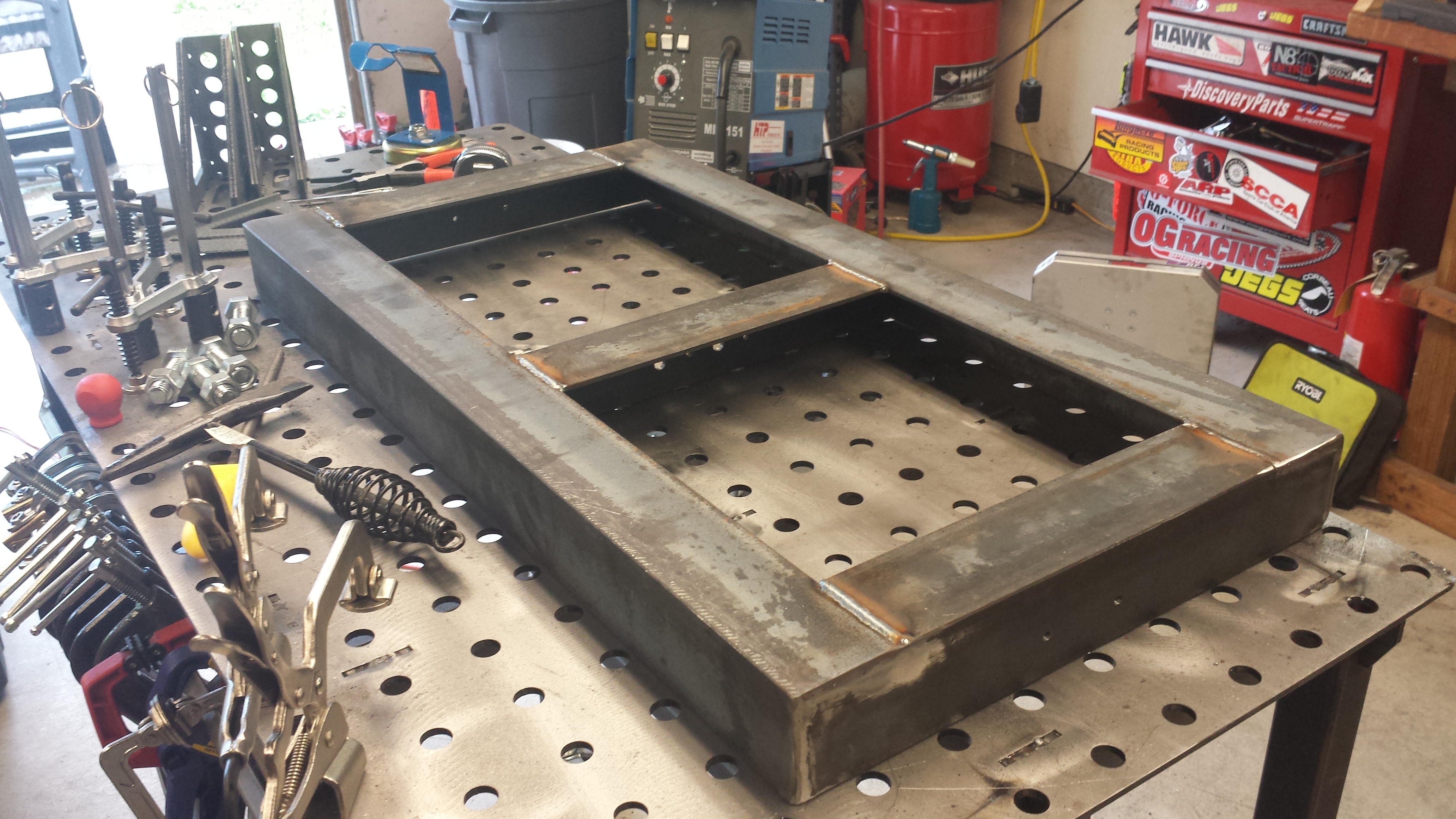
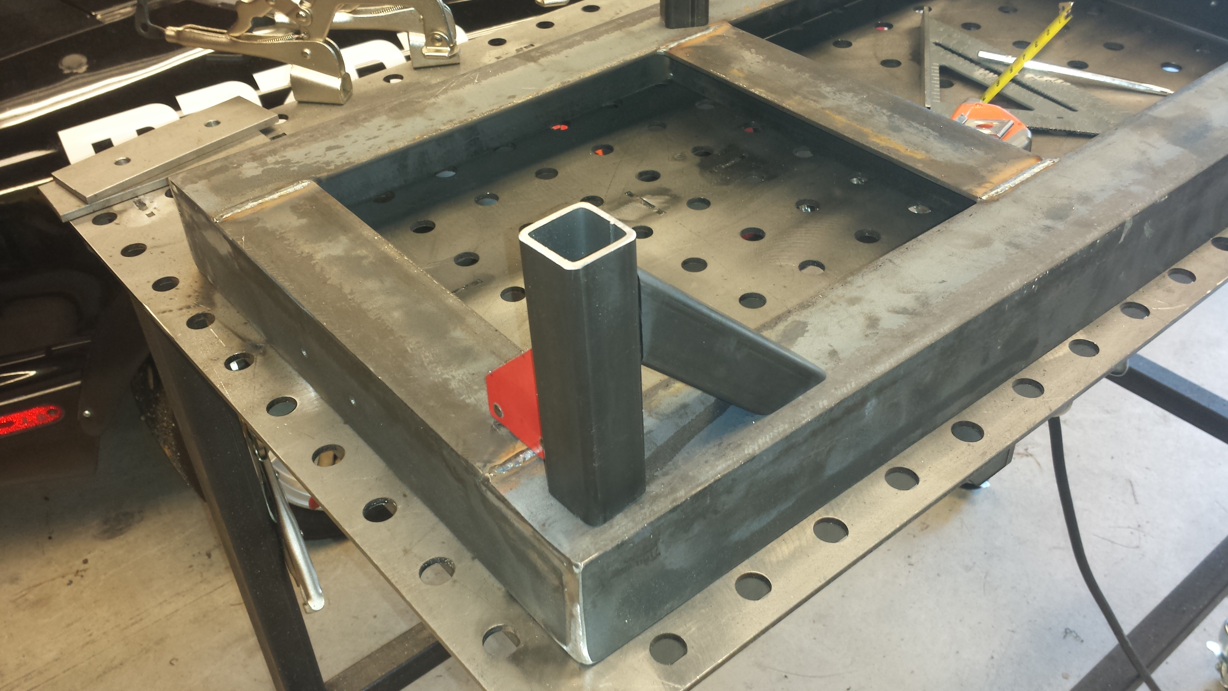
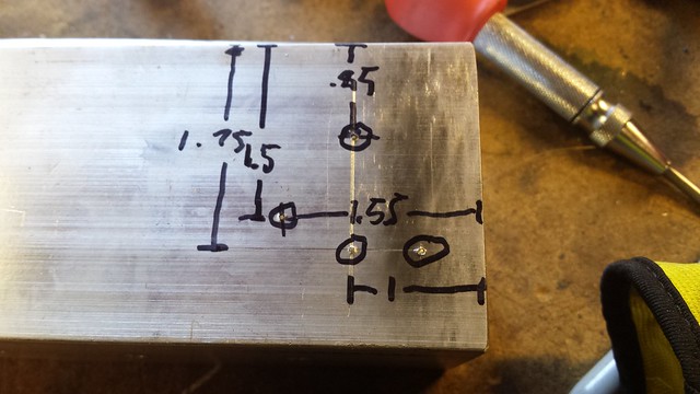
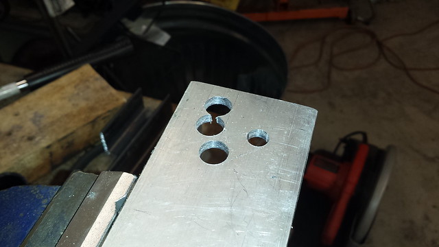
The center support is a length of 1″ bar with 3 holes through it. 1/4″ on one side for the bolts, and just about 1″ on the bottom to allow a 10mm socket with an M6 nut to be inserted from the bottom.

20170425_111651
20170530_215901
20170531_134710

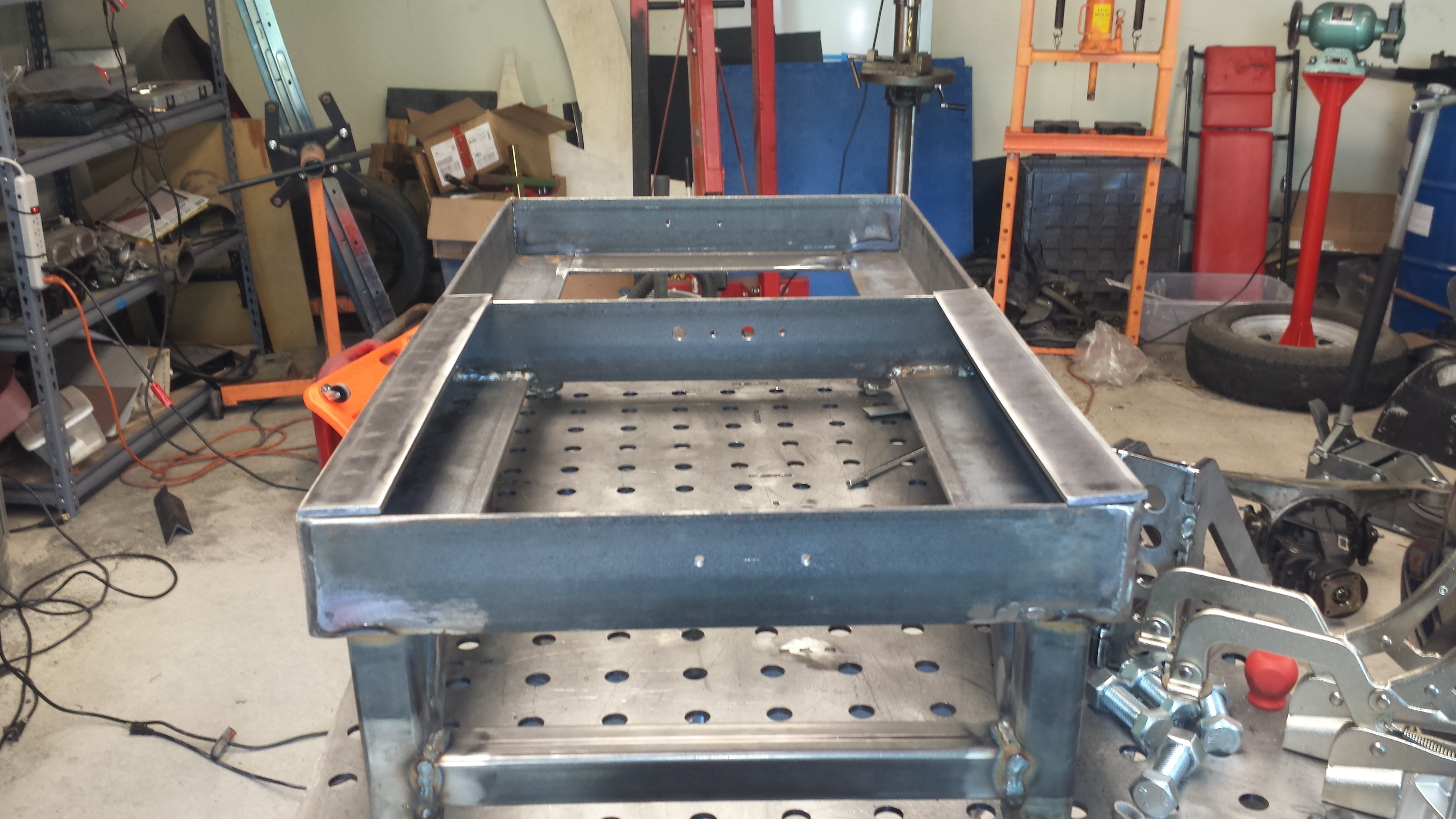
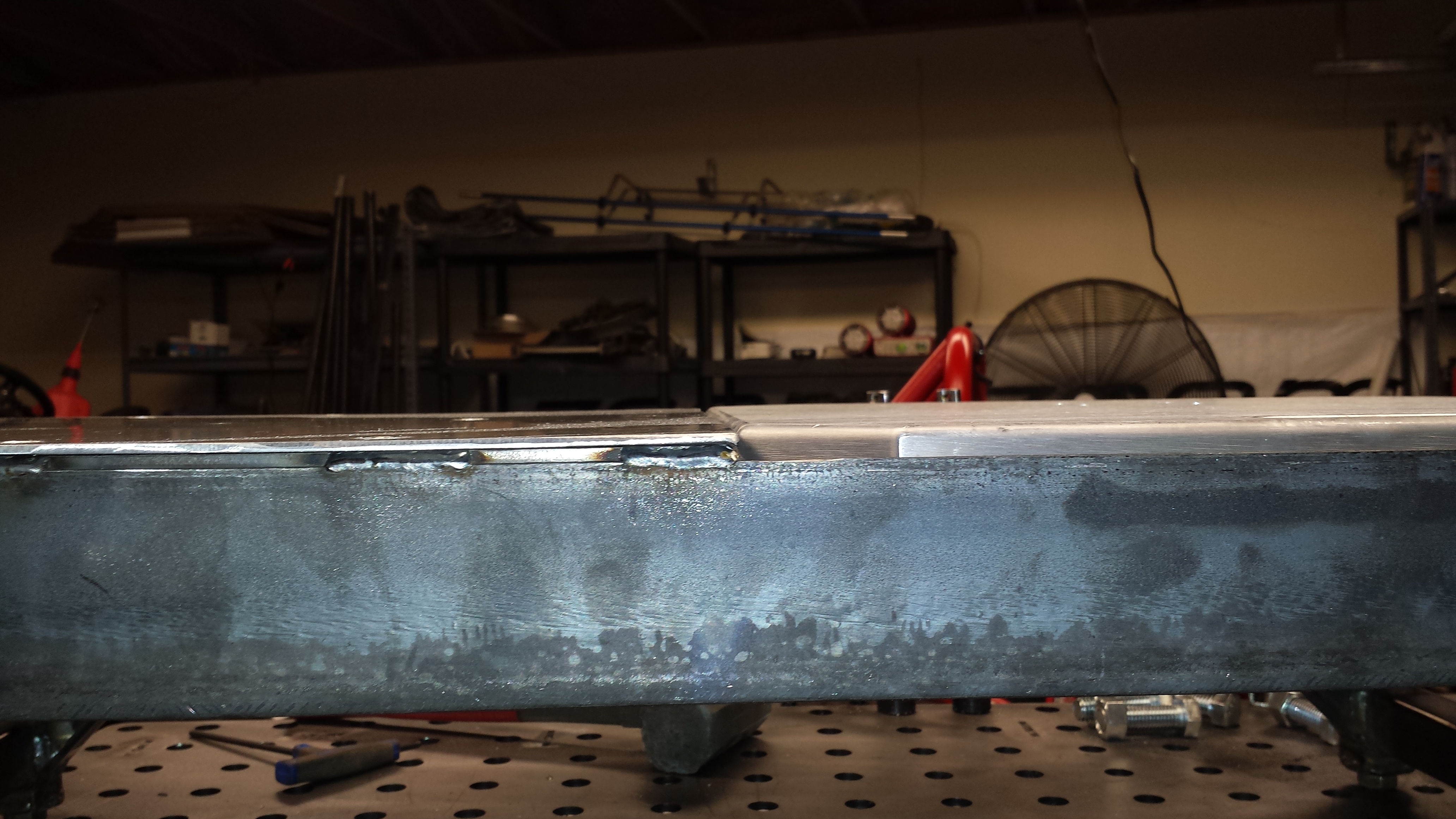
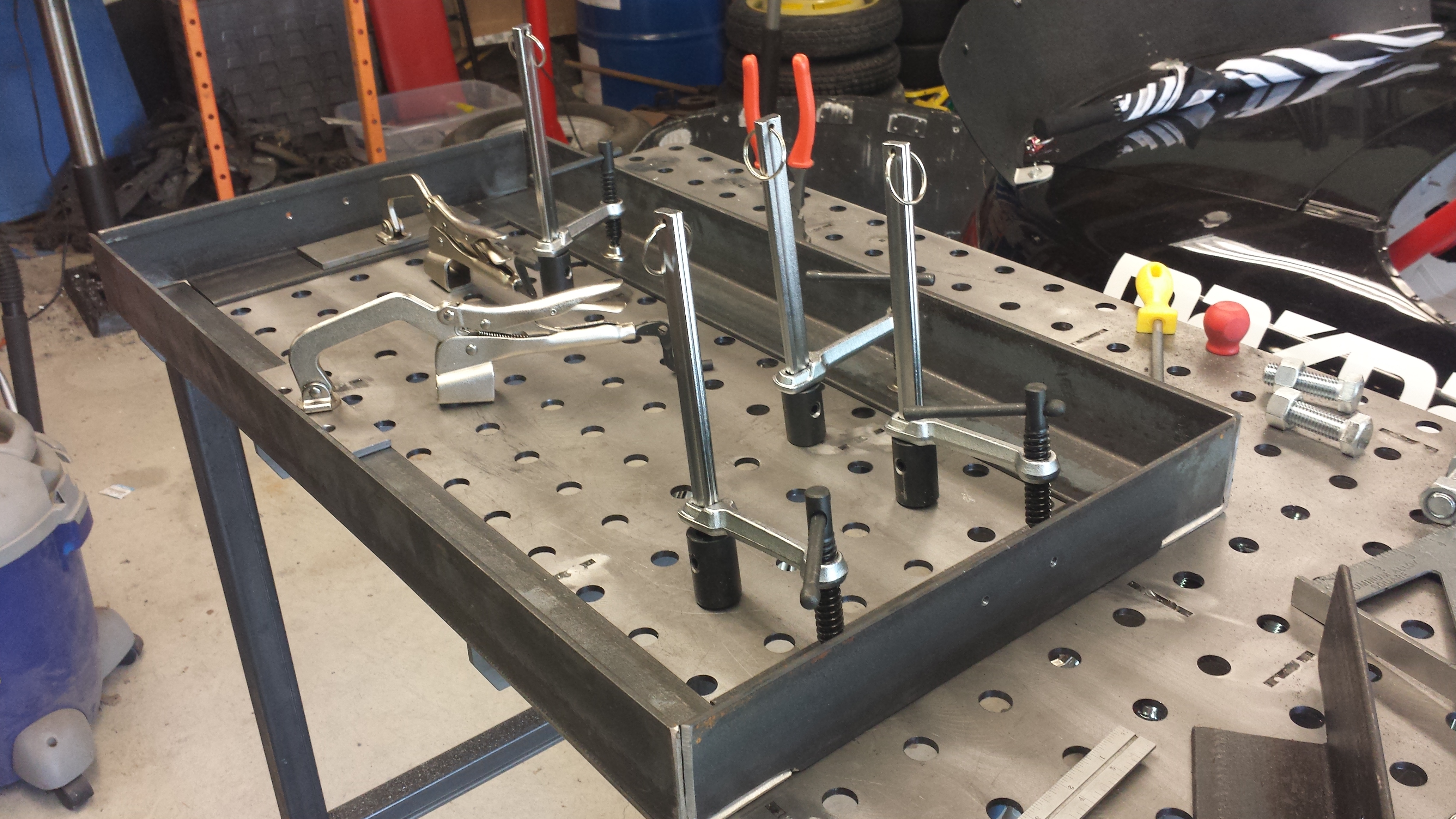
Once the 2 sides were done, the next challenge was fitting up the middle support tube such that it was dead level with the 2 sides so the floor is perfectly flat. To do that, I flipped the entire frame so that the side-supports were flat against the welding table, then placed the tube in to get tacked up so that the welding table top became the reference surface for the whole setup.

20170425_181245
20170425_184036

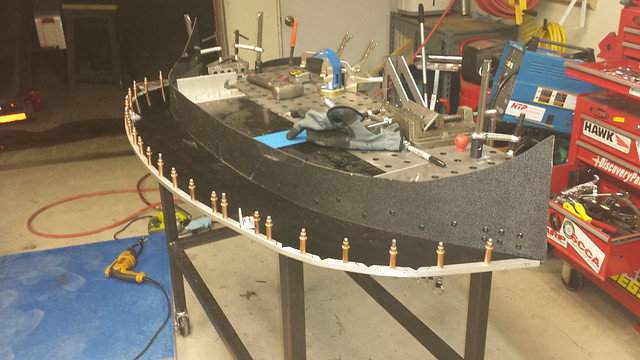
With the frames completed, it was time to fab up the floor. After rough-cutting it, clamped it to the frame and drilled the 3 central holes as they can be accessed from underneath. The challenge, however, was to get the position of the 6 holes on the sides that were covered up by the angle iron.

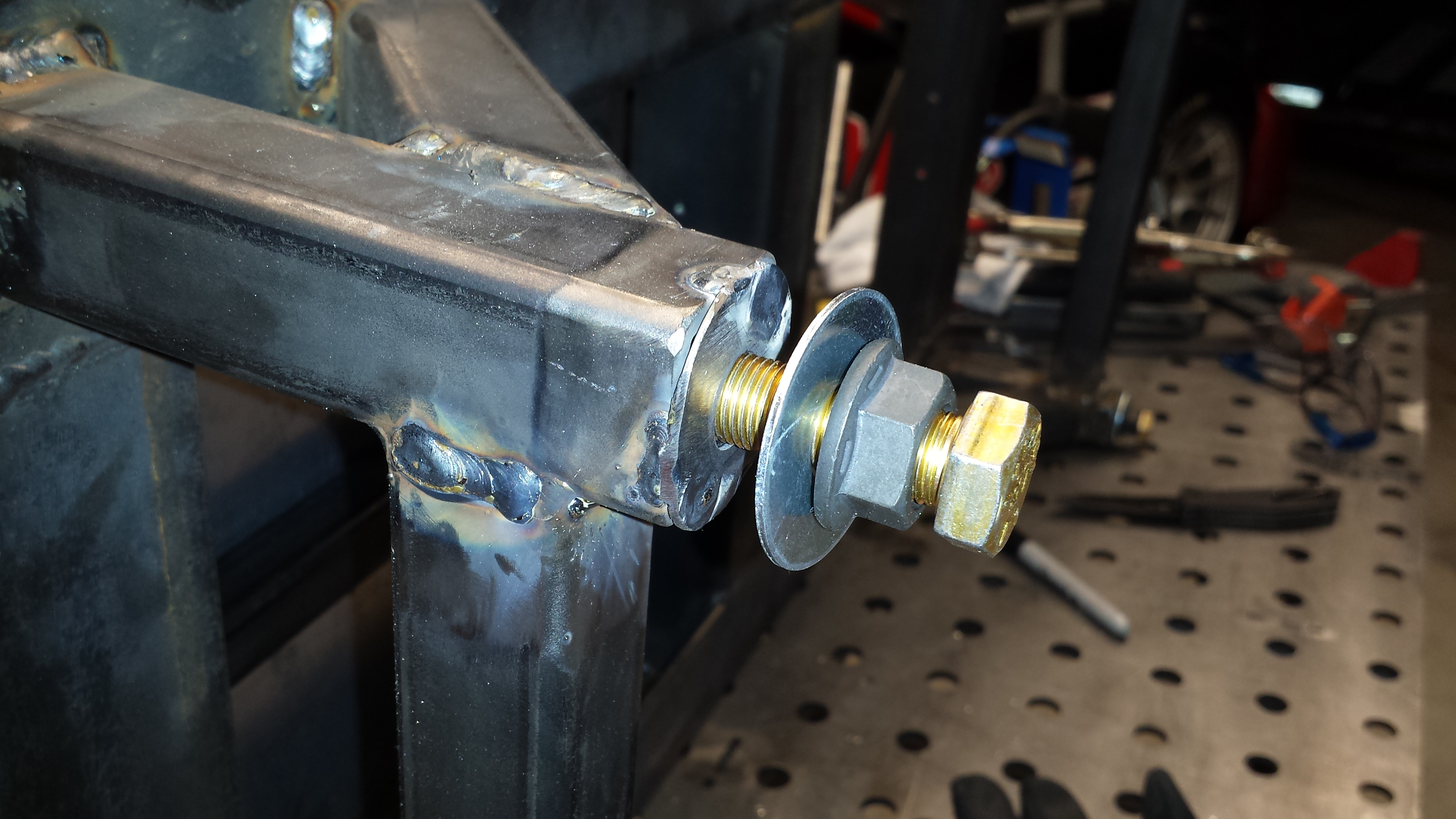
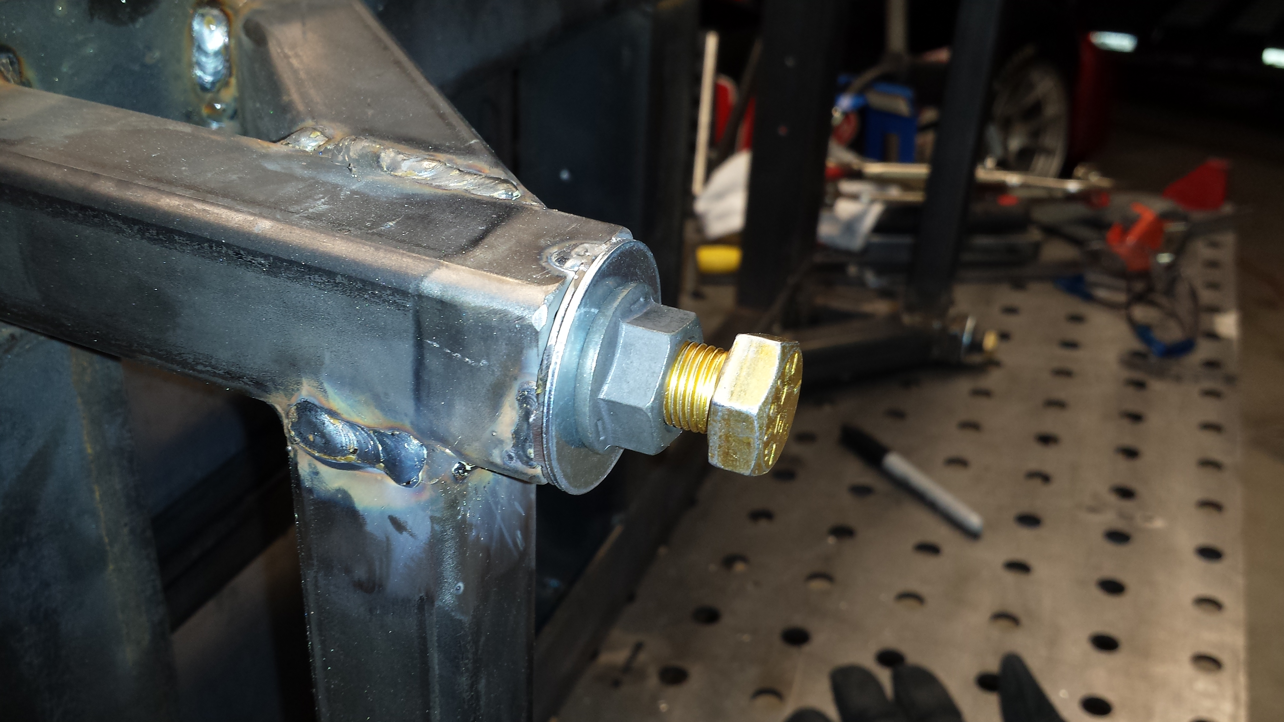
This is where a DILYSI Dave hot tip came in incredibly handy. Long ago when I was building the new Seat Mounts, he suggested making some blind transfer punches out of some bolts. I made up a few more so I’d have a full set for this job. I threaded them into the holes, then bolted down the 3 central bolts so that the floor would be in the correct place, then gave each location a sharp whack with a rubber mallet to mark its location on the aluminum sheet for drilling.

20170425_214112
20170425_214112
20170425_215455

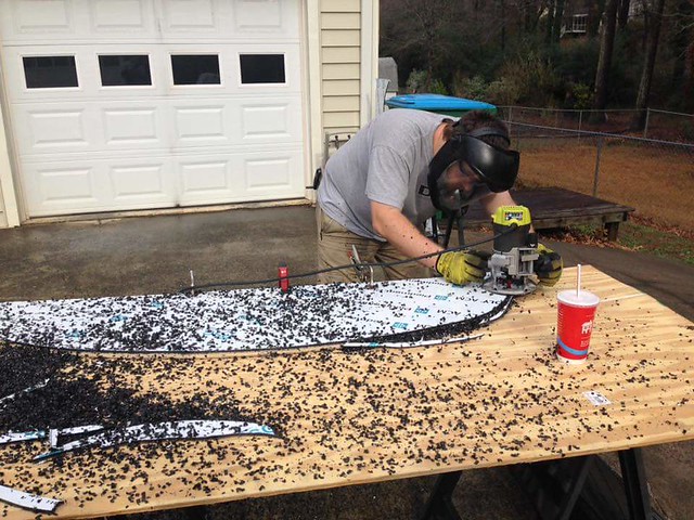
With the prototype nearly complete, I wanted to do some strength testing (ie: dropping the car on it vigorously a few times) to make sure there weren’t any glaring issues:

20170425_220310

And since I was painting the new Saw Stand, I figured I might as well hit this one with a coat of paint. This, it would turn out, would be a mistake.

20170505_180015

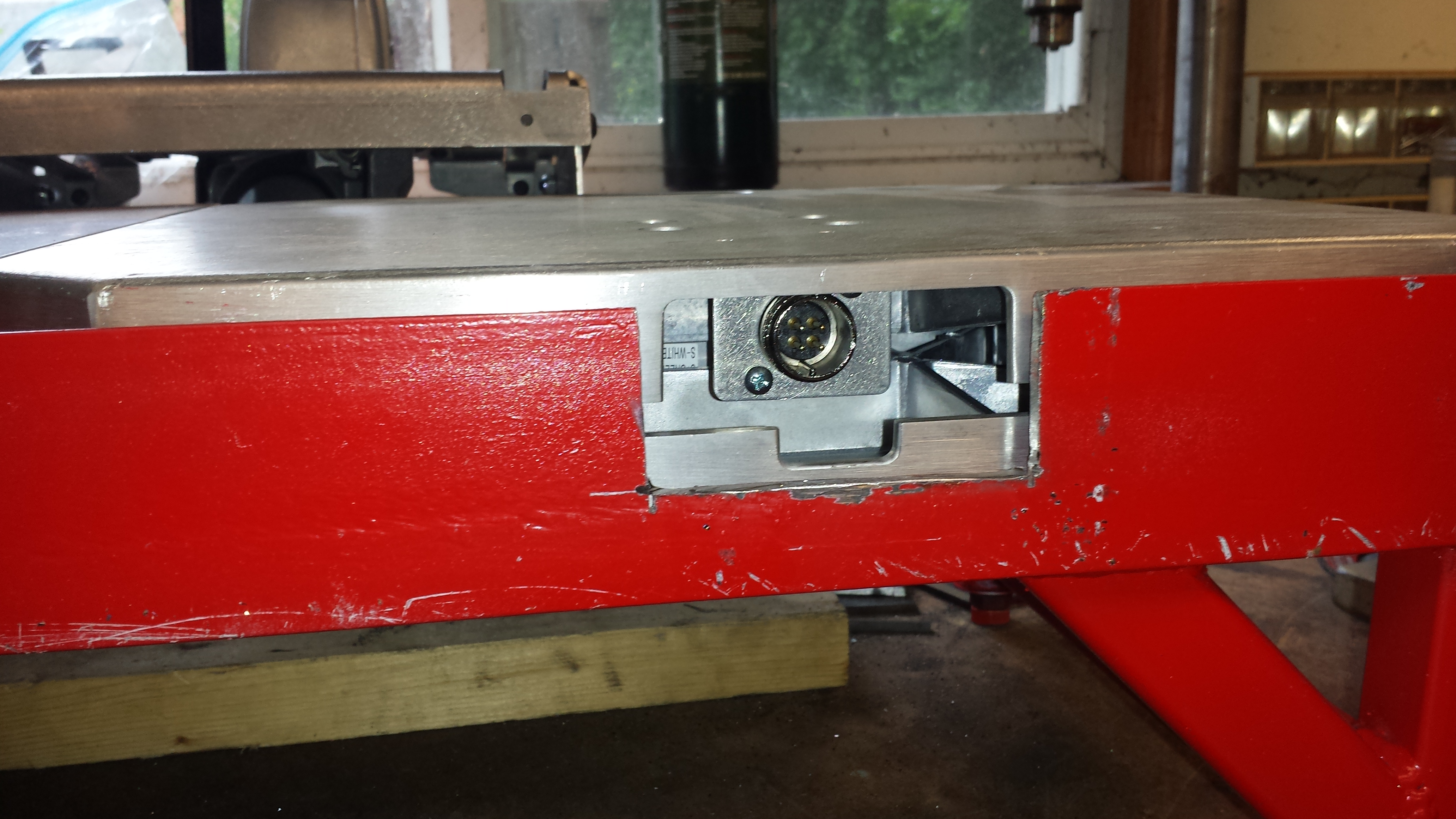
The keen eyed will notice 2 glaring omissions at this point (the point at which I thought I was done with this…). 1. There is no provision for the cable for the scales to pass through, and 2. There are no wheel stops. The commercial ones don’t usually have wheel stops, but they’re much shorter so were you to roll the car off of them, the likelyhood of them damaging the car is fairly low. These are very tall, and VERY strong. As such, should the car roll off of these, it would be ugly.  I’ll address these next.

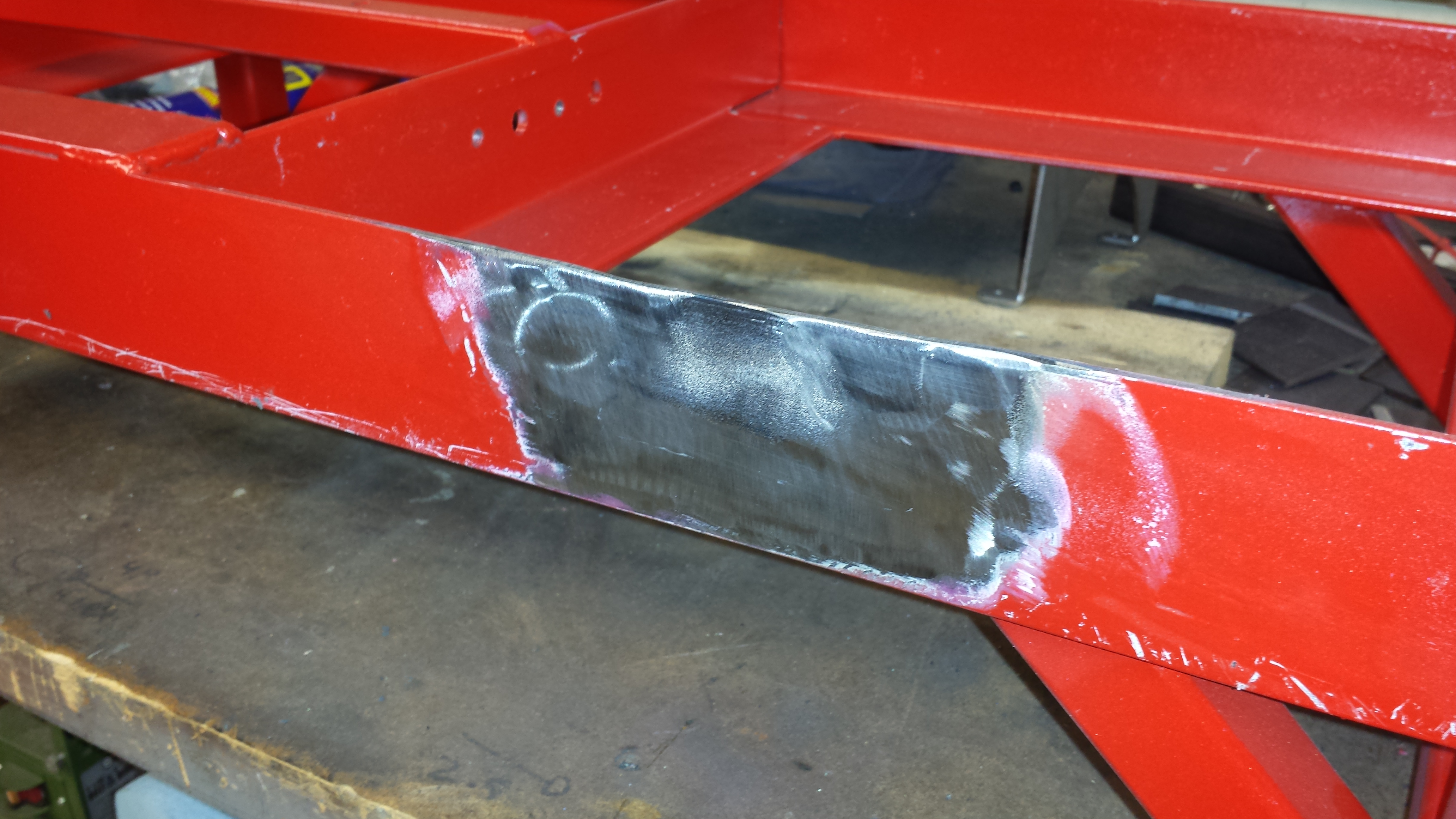
First up is a notch for the cable. Attempt number 1 was…. well… fugly. I tried doing it with and angle grinder and the results were bad.

20170521_153950

It was at this point that the true value of a welder came into play. That was ugly enough that I decided to un-cut steel.

20170521_203640

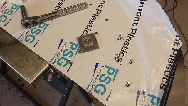
After a rethink and some consultation, I decided to use a hole saw instead. Normally this wouldn’t be a problem, however at this point, with the frame fully assembled, it was a bit late in the game. This is by far the dumbest thing I’ve ever chucked up in the drill press, but damn if it didn’t work!

(I’ve no idea why this photo shows up sidewards. Click the picture for the right-side-up image)

20170522_085952

Thankfully the results were most excellent. After a little cleanup of the sharp edges and corners with a flap disk, I was very happy.

20170522_090728 
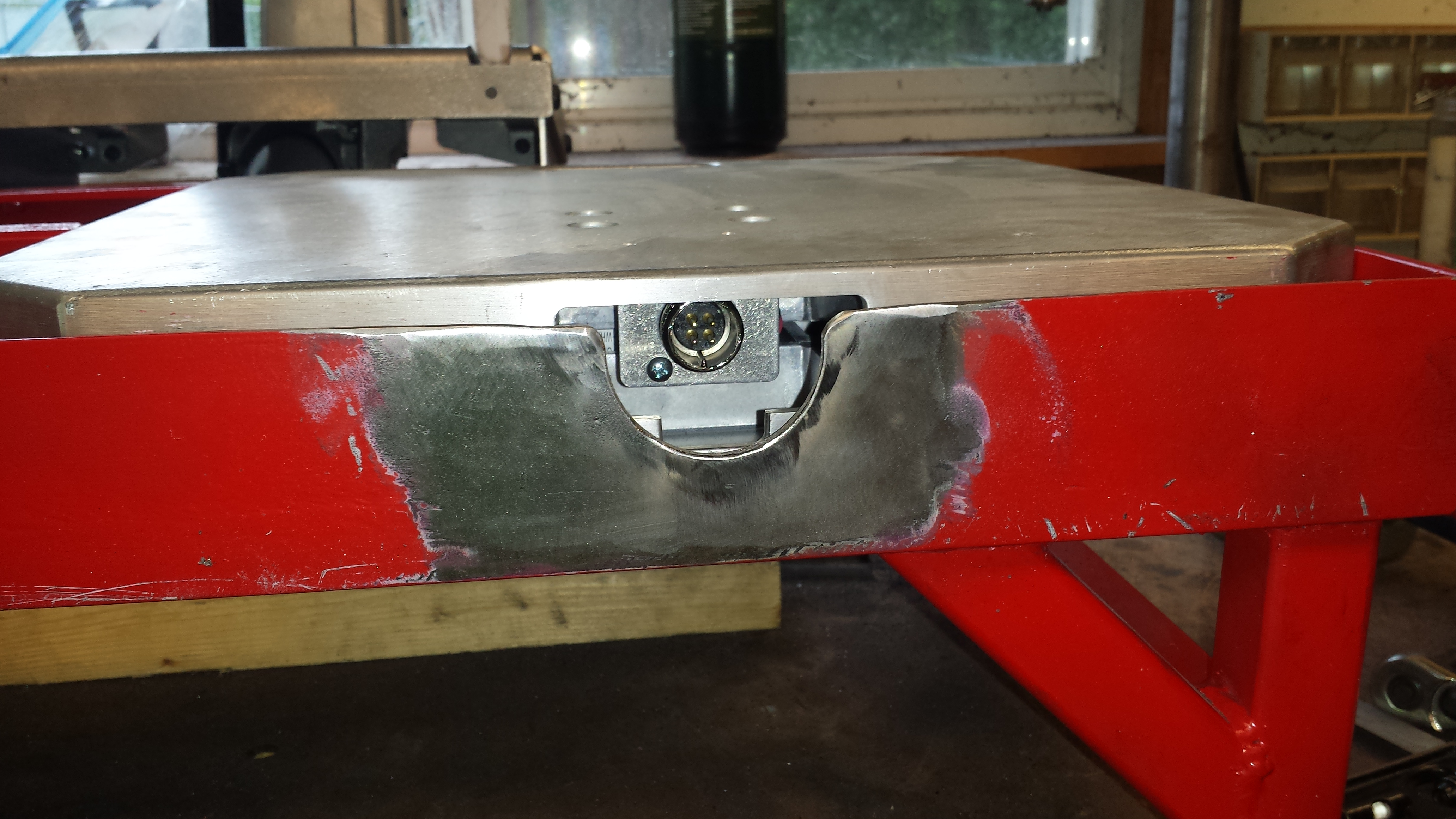
Now that I know where the notch needs to go, subsequent cuts were FAR easier. 20170522_130536

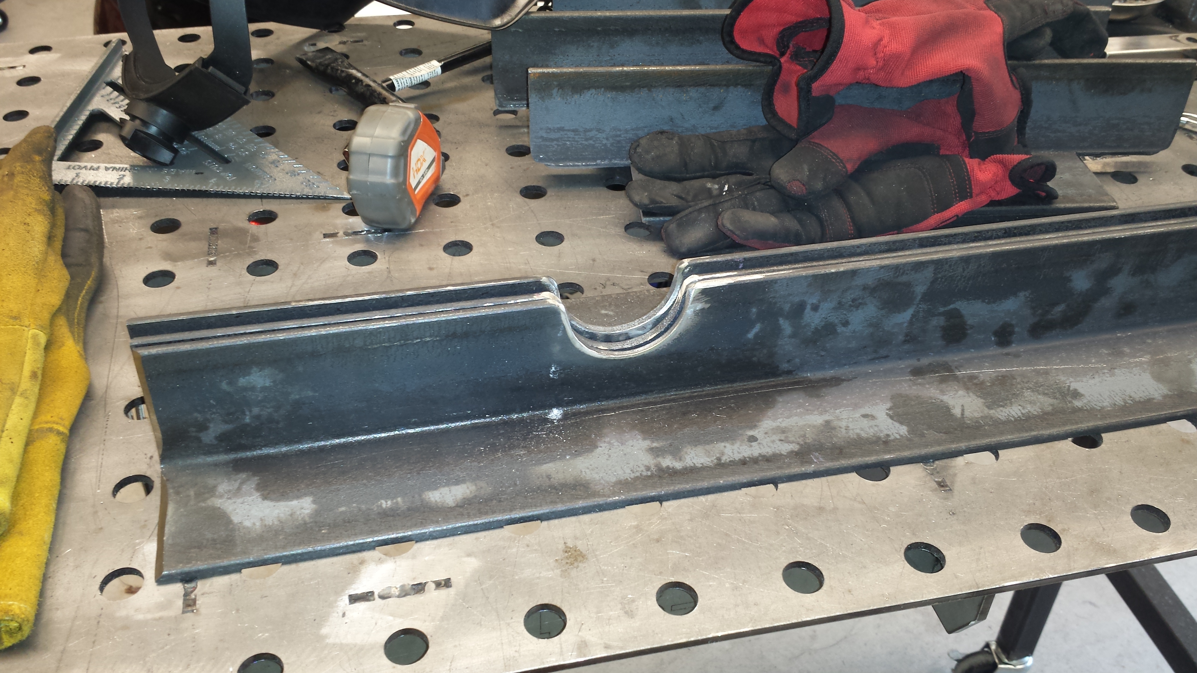
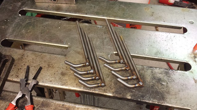
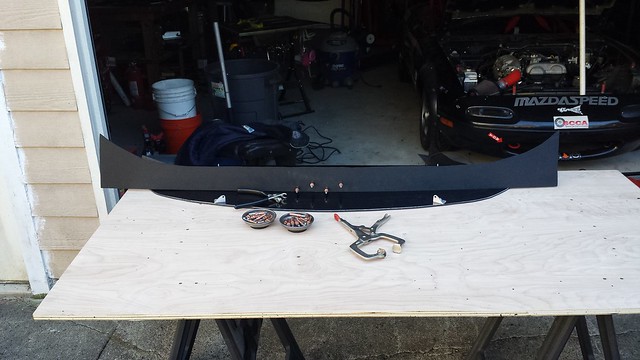
On to the tire stops. After a bit of figuring and evolutionary engineering, I ended up with an easy to fabricate, dead simple solution that will 1) stop the car rolling off the ends, and 2) still allow the stands to stack together to minimize the space they take in the shop.

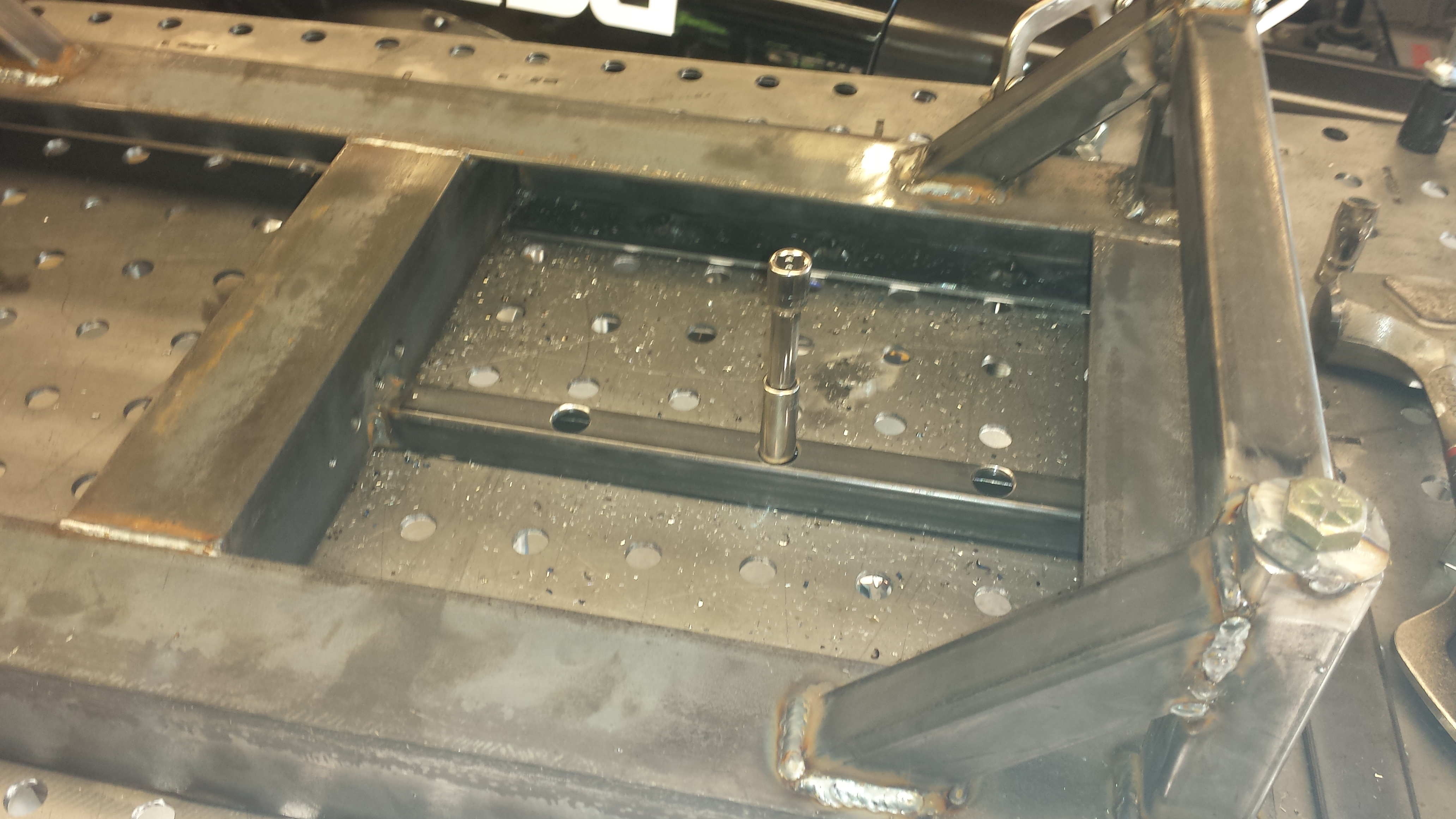
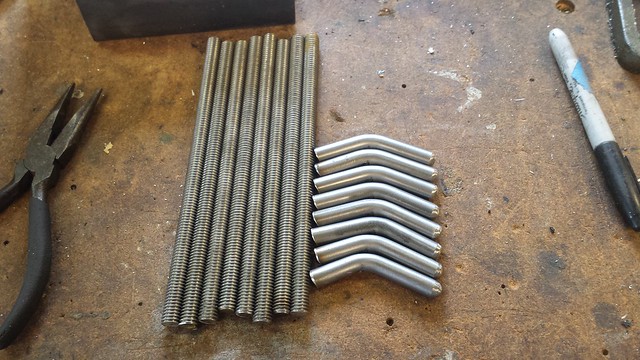
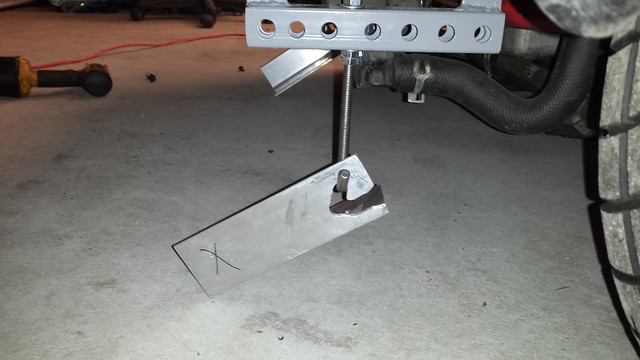
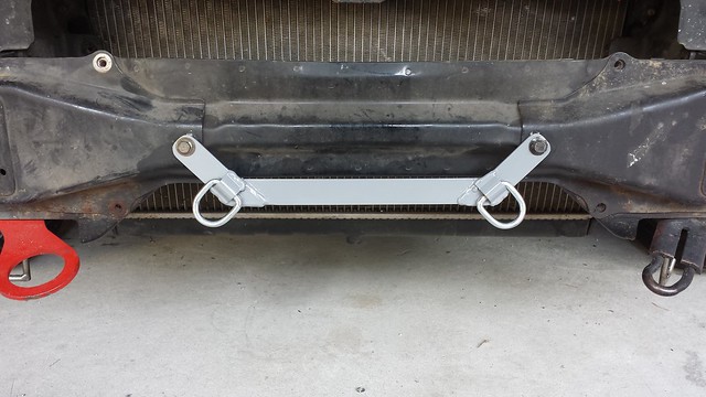
Part the first is a 2″ length of 1/2″ OD tube welded in the center of each end of the frame:

20170531_175720

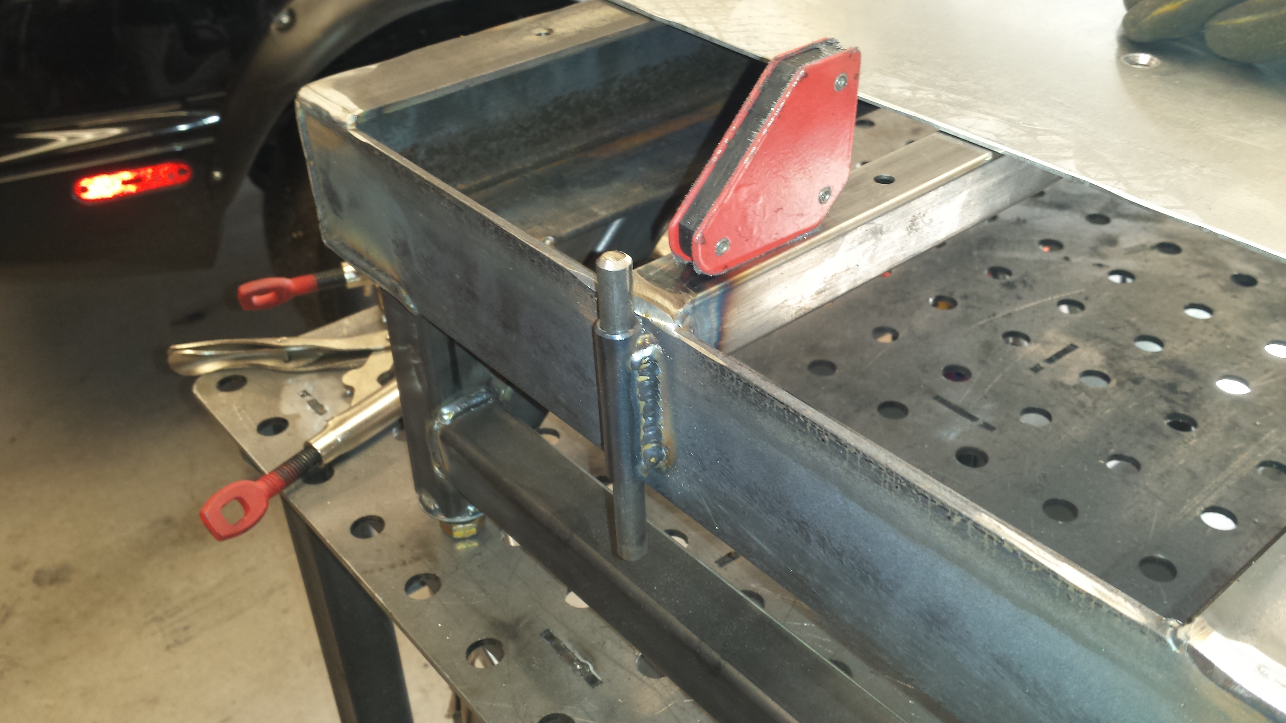
Next is a 6″ length of 3/8″ steel rod, with a bend around the 2″ mark and a bullet nose ground in on each end. The bend is so that they won’t just fall through the tube, and it leaves a ~4″ step that would take an immense amount of force to get the tires over. If you figure out a way to do that, you do your alignments far more aggressively than I.

20170603_143414

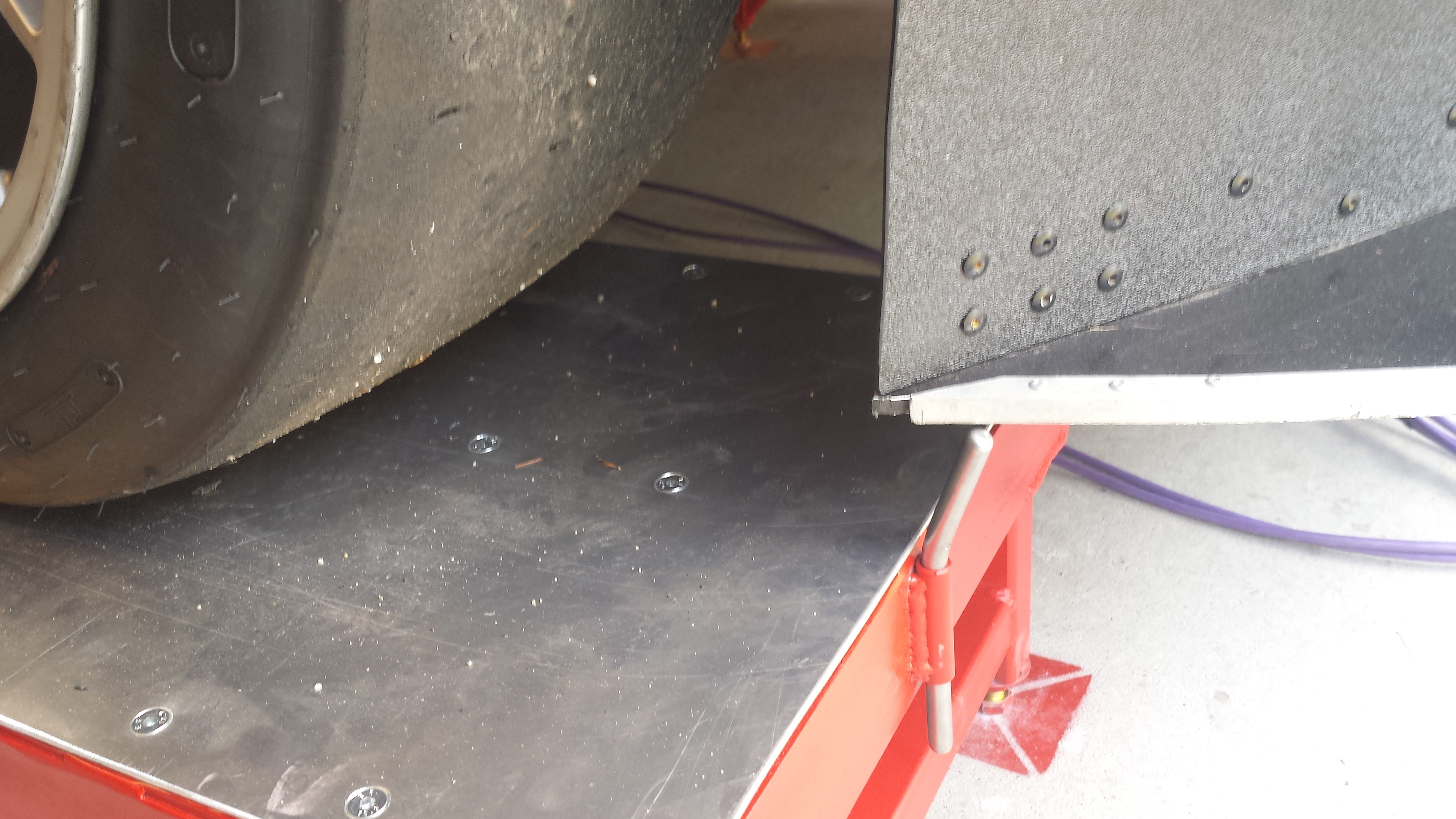
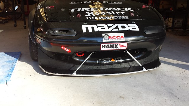
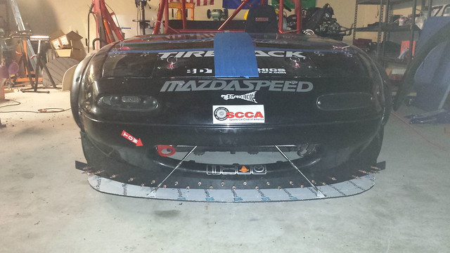
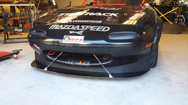
The short side / long side has an added advantage that I wish I could take credit for but in reality was a complete, but happy, accident. Up front, that long post interferes with the splitter when rolling the car back and forth between the scale and the roll off pad.

20170617_140137

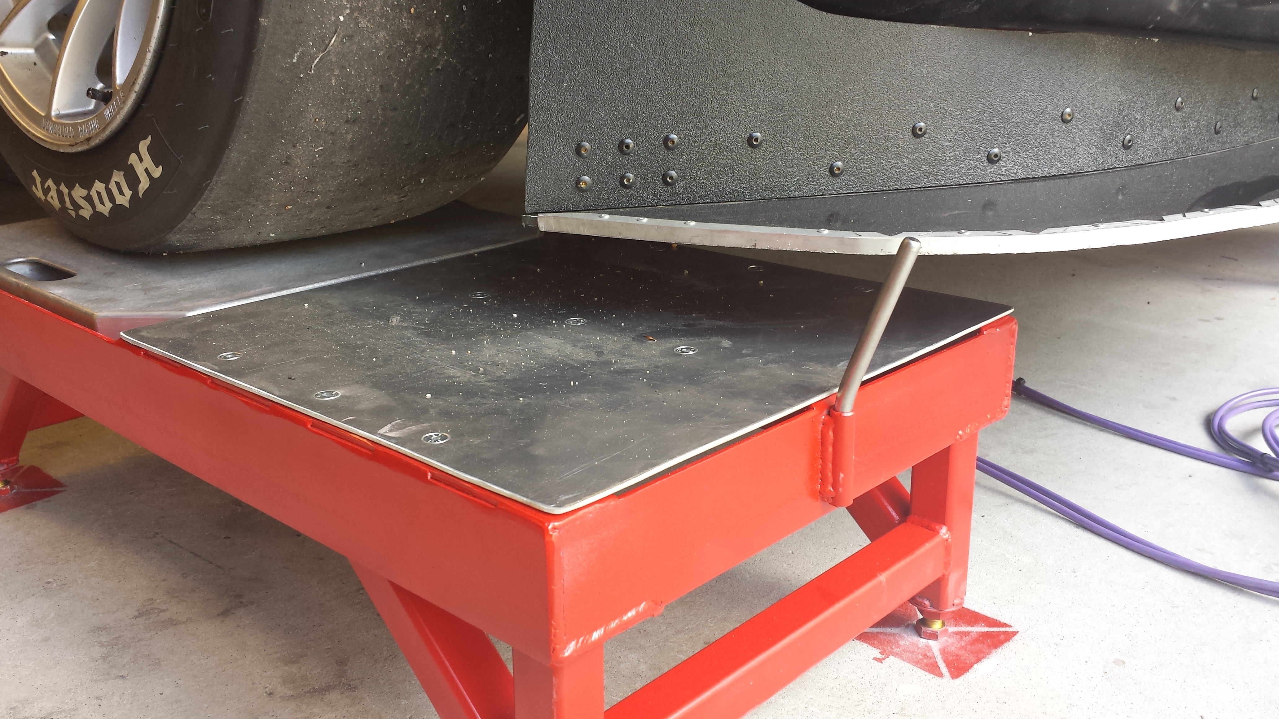
With it flipped upside down, there’s still plenty of a step to stop the car (plus the taller sides are still up at the rear), and the splitter clears easily. I love it when a plan, accidental or otherwise, comes together!

20170617_140226

Now to just do all that 3 more times.

To be continued!

Part 1
Part 3

Setup Stands Part 1 – The Frame Job

Many moons ago, a buddy posted a few pictures to Facebook of his car on some setup / alignment pads. My curiosity piqued, I reached out and got a bit more info from him, as something similar would be phenomenally useful. I’d looked at commercial options for these, but they are prohibitively expensive, and John’s homebuilt pads looked pretty close to what I wanted for a lot less money.

After a great deal of figuring and bouncing ideas off of engineer friends, it became clear that a set could be made that would also incorporate setup scales, for relatively little cash (and a great deal of time….so, so much time). Initial designs were drawn up and steel ordered.

What follows is going to be a boatload of photos of various stages of the build. It was a very very long process of evolutionary engineering and problem solving, but now that I know how to build them, additional sets will be made relatively (and it is very relative, because they’re a ton of work) easily.

First step: getting a bunch of steel home. I had various pieces cut more or less to length, as I didn’t know exactly how they would go together but had a general feel for at least what the long legs needed to be. The rest were cut to fit in the back of the truckster to get it home.

20170416_203127

Lots of measuring (way more than twice), cutting, coping and beveling later, and the first frame was roughed out.

20170420_133843

The scales will sit on the side with “floor” on all 4 edges, and the rolloff pads will go opposite them.

20170420_145711

Cutting 45 degree miter joints would have been far easier from a fab standpoint. However coping the joints has 2 very big advantages: it leaves nice, flat areas on each end of the “long” side of the frame for the legs to sit on, and with that, there is a lot less strain on the welds and puts everything in compression, with the welds mostly holding the pieces together, and not supporting the weight of the car.

It’s not that I don’t trust my welds, but with something that needs to hold the weight of a car from crushing me to death, I will take every bit of added strength I can get.

20170420_145752

A quick test fit was very encouraging. My measuring a dozen times lead to a fit that allows the scale pads to rock in and out easily, but not enough that they can move around too much.

20170420_170756

Mocking up the legs:

20170421_121013

20170423_150017

Got the rest of the gussets and the horizontal supports done.

20170424_172751

A design requirement was to have feet at each corner that will allow the full set to be leveled. The first step of that are these that make the bottom of the legs, with the threaded nut inside the leg. So, weld the nut to the washer, then weld that assembly to the leg.

20170522_204237

The rest of the parts stackup.

20170425_233916

This once again goes into the strength of the thing. Once the jam nut is tightened up, all of the load is on the big washers at the bottom of the legs and the bolt, and virtually none of the operating load is on the tack welds securing the nut on the inside of the legs.

20170425_233952

With the basic design roughed out, we’ll work on the roll off pads in Part 2.

To be continued….


Part 2
Part 3

Splitter Leading Edge Reinforcement

So far I’ve been loving the new splitter, however because of the nature of the DiBond, the leading edge is a bit soft and has taken a few licks. I borrowed an idea from a couple people in other classes, and put a reinforcement / trim strip along the leading edge of the splitter.

Lowes sells aluminum channel to “trim” 1/4″ ply (which happens to be the same size as the dibond my & their splitters are made of)
This will make the leading edge much less of a wear surface. Bending and pie-cutting this stuff in a way that doesn’t cause stress fractures, and slotting it to clear the mounts is a royal pain, but it will add a ton of longevity.

20170328_232934
I reinforced both the front and rear edges. The front is to protect the leading edge of the Dibond. The spar across the rear is to add a little more rigidity along the ‘long’ side of the splitter.

20170404_180823

20170404_181236

The fact that it looks a little Mad Max-ish doesn’t hurt either 😀

Aero: Front Splitter V2.0

After last season, Splitter V1.0 was seriously trashed. Placed on a flat surface, there was almost 2″ of bend across its width, so at a minimum I had to replace what was there. At a maximum, it was time for a complete rethink.

It was definitely time for a complete rethink.

So, based on what I’d learned making and repairing the first one, I set about replacing every single component save the 2 quick release pins. I didn’t intend for it to be that thorough of a redesign, but during the offseason, if there’s opportunity for improvement “while I’m in there,” you might as well take advantage of that.


Part 1: The Rear Chassis
Mounts

These were the pieces I had far and away the most trouble with last season. They were not adjustable, so once I eyeballed the height the 1st time, that’s where they lived. Furthermore they were difficult from a maintenance perspective, a once you hit something hard enough to bend them, the only thing to do was attempt to beat them straight with a hammer, or completely re-build them. There had to be a better way.

This piece took a bit of evolutionary engineering, but I think the result will be up to the task. You can see V1.0 on the left, bent in a couple different directions, and very unwilling to be bent back straight (especially along the longer edge).

20161111_140926


Instead of having a single piece mount, I decided to make a very strong mount to the chassis, with weaker sacrificial hooks to take the brunt of any larger impacts. The hooks are very easy to remove & replace, and to manufacture. The hooks are simply a length of 3/8″ threaded rod, and a short bent piece of steel round bar.

20170116_135941


A quick bit of welding and I have (what I hope to be…) a season’s worth of replacement. Hopefully more.

20170116_202426


After a bit of time on the drill press and a coat of Machine Grey, and the chassis mounts are done.

20161124_161043


Part 2: The Rear Splitter Mounts

The Hooks on the splitter that held it onto the chassis mounts also took a beating last year. Also, their geometry meant that with a good bit of load on the front, the rear hooks would lift off of the mounts. Unlikely to happen under real world conditions, but also suboptimal.

Given that, I went with stronger material (1/4″ Aluminum, up from 1/8″), and a more angled hook design that keeps it located both horizontally and vertically.

After a bit of figuring, this was the design I came up with. The bottom 3 holes are 1/2″, and the top one 3/8″ to tightly hold onto the chassis mounts.

20170107_134517

20170107_155441


After a bit of cleanup and fitment testing, these are complete:

20170107_164751


Part 3: The Front Chassis Mounts

The front chassis mount (under the front bumper) has always been a pain. It allowed for no deflection (which meant bent front splitter struts), and because they only had 1/4″ holes for the quick-release pins, they were very finicky to get everything lined up with.

Inspiration from this came from a relatively prestigious place: The Dodge Viper ACR. I noticed that it had a mount that’s basically only rigid when downward load is put on it (ie: aerodynamic load), but would allow for upward deflection (ie: for off course excursions) to prevent the struts from taking all of that strain.

Here’s what I came up with. The D-rings are completely rigid in tension (ie: aero load), but will allow for deflection (ie: bigger cone strikes or bottoming) to hopefully prevent bending the struts. As an additional bonus, the target I’ll need to hit in order to mount the quick release pins is orders of magnitude larger, which will make mounting the splitter at the track far easier.

20170115_120636


Part 4: The Front Splitter Mounts & Struts

The front splitter mounts did the job, but were a little small in surface area against the splitter. They were also short legs, meaning that the nuts for where it bolts to the splitter and where it bolts to the struts were practically on top of each other. I used the miter-saw I received as a Christmas gift to throw these together (shown with a spare set):

20170109_140953


I also found some turn-buckle rigging forks on Amazon that, with a little bit of drilling and welding, I was able to make into a pair of new front struts.


Part 5: The Splitter and Final Assembly

Finally, we get to the splitter itself. Using the laminated sheets of DiBond ended up being both a ton of work, and fairly ineffective. After the rigors of the season, the bottom sheet was fairly worn down (another casualty of non-adjustable rear mounts) and it never was as stiff as I would like.

After consulting with some buddies who know more about this stuff than I, I decided to go with 1/4″ Dibond. The single 1/4″ sheet is far sturdier than the laminated 1/8″ sheets.

The first step was to make cleaner (and thicker) buck for the splitter. The lines on the 1st one weren’t all that clean. This will make for fairly quick & easy replication with a router & a flush-trim router bit.

20170117_152031


I picked up a brand spankin’ new sheet of 1/4″ Dibond, and we managed to cut 3 splitter blanks out of it, then trimmed them down with the router. It’s a super dirty process, but it is super effective.

FB_IMG_1485110592446

20170121_150148


Instead of using sections of the Home Depot Racing Supply paver edging for the air dam, I went ahead and used the whole one (so it would be more rigid), then we riveted the original air-dam to it to use for mock up, to then make a pattern (and buck) for a new design:

20170127_112707

20170121_182454


Once all the mock-up was done, it was time to disassemble the whole thing and put the “real” parts on. All of the parts were mounted using elevator bolts.

I made a spacer to use with a nut and a washer stack to pull each elevator bolt into place:

20170127_103449


After a bit of sweat equity, this is what the bottom looks like. The nice thing is that they have very thick bases, which allows them to serve as something of a wear surface without sacrificing too much strucutral integrity, as opposed to using button head bolts, which have much less metal to wear down before they’re rendered useless.

20170127_112100

With the base complete, we used Clecos to temporarily rivet everything together…

20170128_122420


And then finally completed assembly and riveting, and got it mounted in place:

20170128_134644


It was a ton of work but now that I have a good, solid design, replicating it will be relatively straight forward. Hopefully I don’t find any crazy weaknesses with this design that’ll require another complete rethink.