A quick note at the top: For this to fit you’ll really want the KMiata Intake Manifold. You MAY be able to hog enough material out of the throttle body spacer, which interferes with the alternator side spherical bearing, but the KMiata manifold has plenty of room for everything.
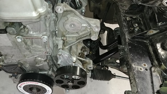
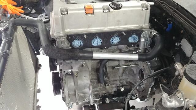
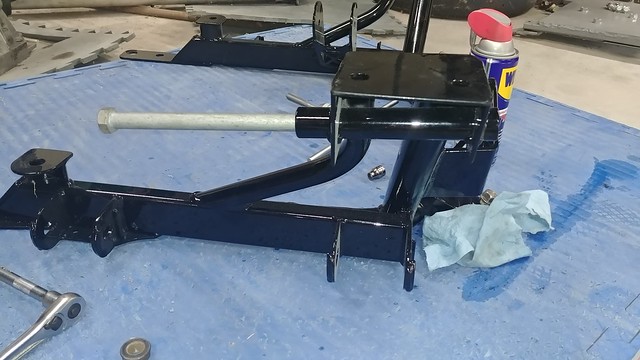
I love the simplicity of KMiata’s 4-pulley setup, but I’m not really happy with the tensioning setup. I’ve no doubt that it works, but hear me out: the K24a2 alternator bolts in with 3 bolts, perpendicular to the block. In a stock configuration, there’s a big, sprung(?) idler / tensioner pulley in the system. Since that’s gone, this setup uses washers you can see in the pictures between the alternator and water-pump housing to set the tension. Servicing any part of the accessory drive involves removing the idler pulley and, in my case, 10 washers (3 on each alternator bolt plus an additional C-shaped washer I made for the top bolt to put the last bit of tension the belt). Reassembly involves dealing with those 10 washers and putting the idler on at the same time without stripping any bolts or losing a washer.

That works fine (…ish…) if you’re doing this in a clean workshop. I can’t help but picture myself trying to fix an alternator or water pump in a wet / dirt / gravel / grass paddock space at a track or on the side of a mountain, and losing half of those parts in the dirt.
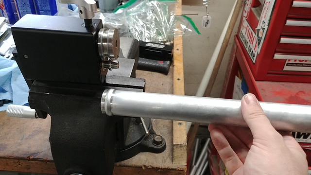
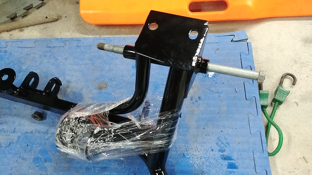
So, while I was able to get it tensioned (with the help of a pry bar and the aforementioned C-shaped washer), some more work was needed on that front. I had resigned myself at this point to simply turning up some spacers on the lathe to use instead of washers, as they’d be much easier to manage (and I could make a spare set, when it came to my attention that the Water Pump Housing from a K24z3 used a single lower bolt that runs parallel to the engine that, with some creativity, could be used as a pivot. In the stock configuration there’s a block that bolts the top of the alternator in place and it uses a sprung tensioner pulley, on the belt, but if the housing bolts up, I should be able to use that alternator and a turn-buckle style adjuster at the top to tension the belt.
Nothing’s ever that simple, however. It’s not exactly a bolt on affair.

Problem 1 is the bolt bores are different sizes / lengths. The z3 housing uses 2 long studs (vs 1 long and 2 short), and then 1 long bolt and 1 short (vs 2 long). That’s fairly minor, I just need to grab a stud and bolt. I could honestly get by with 3 bolts, but the studs help when sliding it on the first time when it’s covered in HondaBond so I don’t screw that up horribly.
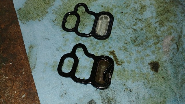
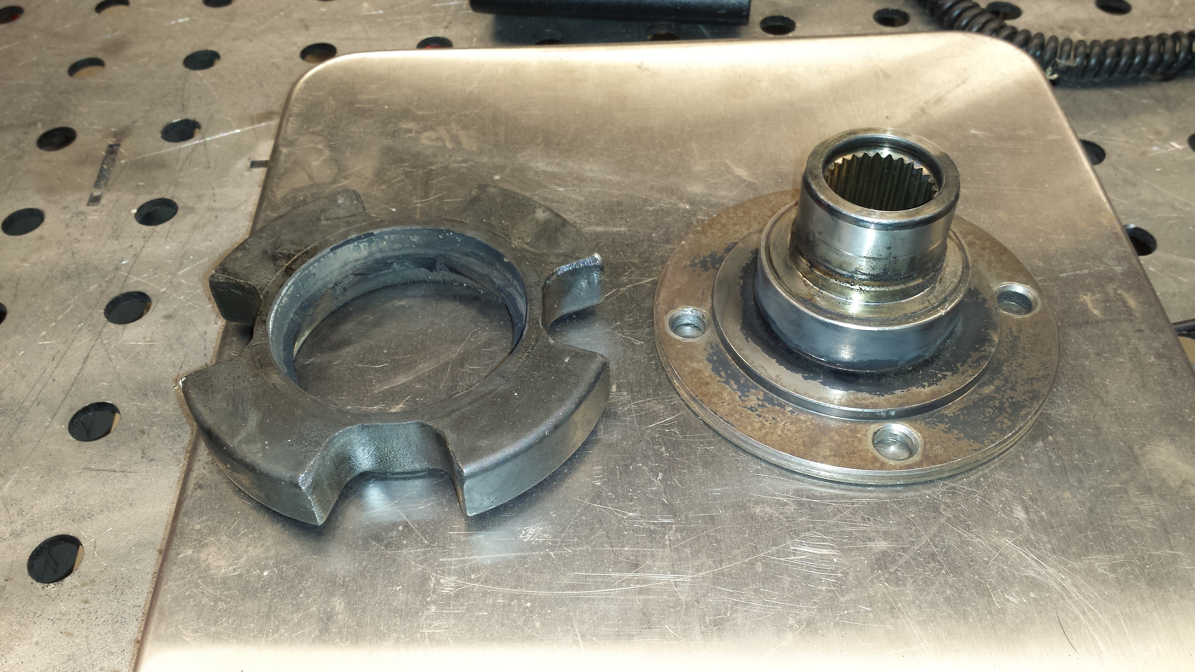
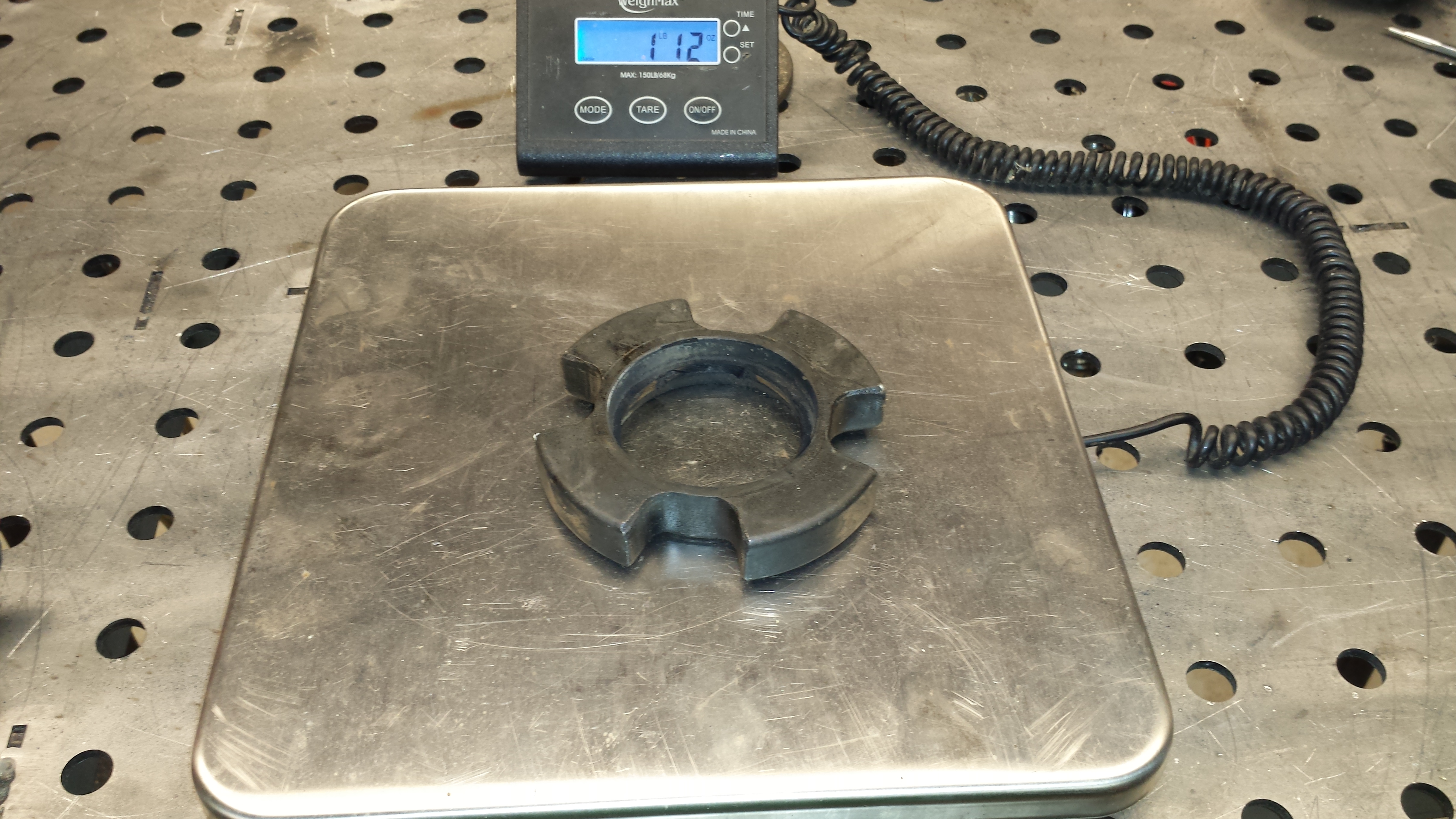
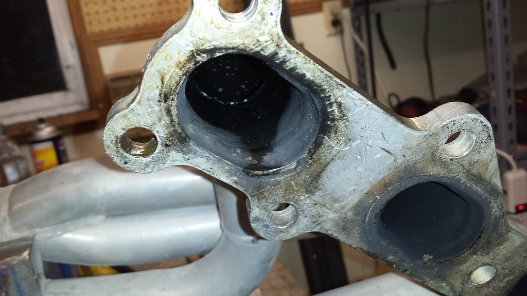
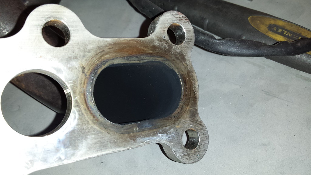
This second problem is bigger, and will require a little help from my friends. The K24z3 housing is on the left, the K24a2 housing is on the right.
The z3 housing uses 3 of the 4 bolt holes the same as the a2, but the one at the upper right (sharpie pointer) is in a different location.
HOWEVER: The hole from the original a2 pattern is *nearly* drilled through in the z3 housing so I’ve got something to work off of.
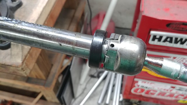
I didn’t want to have my machinist buddy go through all the trouble of milling this thing down if the hole pattern wouldn’t line up, so I used a slightly undersized drill-bit to knock the bottom of that bore out. This way, the original bore is still there to locate an endmill off of to bore it correctly.
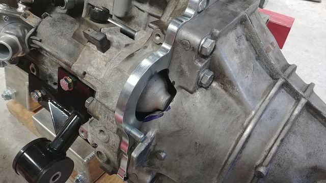
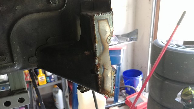
That top bolt is actually tight but it’s sitting on that step in the casting on the back side of the bolt. We (and by we I mean Dave) will mill in a flat for the bolt to sit flat against.
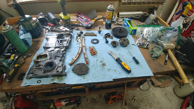
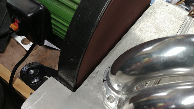
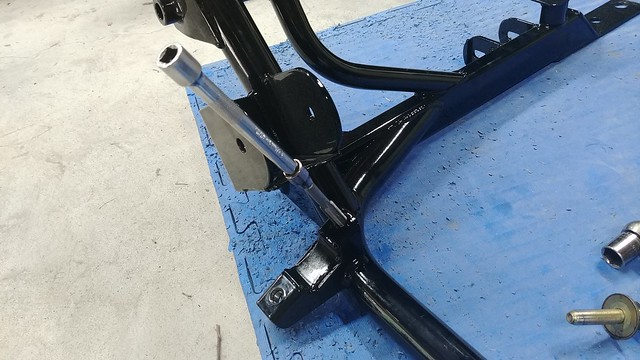
Now that I knew it fit, I could cut the big stock tensioner bracket off of the top of the pump housing and work on a turnbuckle adjustable tensioner.
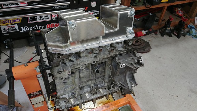
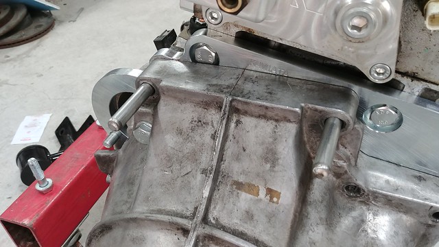
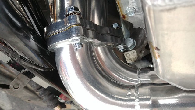
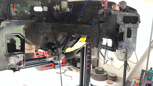
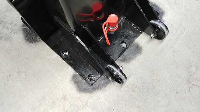
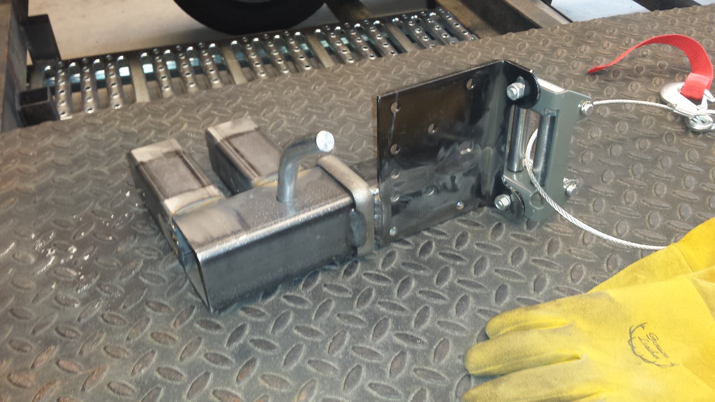
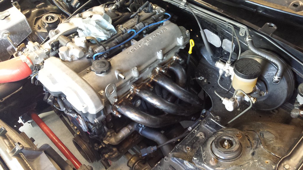
After talking it over with my machinist friend, we decided to try and mount the turnbuckle adjuster to 1 of the ribs of the water pump housing. Here it is all assembled. You can see the machining in the corner for the front upper bolt, and where the turnbuckle rod end mounts.

At full retraction of the turnbuckle (to get the belt off, for example), the engine-side rod end was binding, so I turned up a 3/8″ spacer on the lathe to add some clearance, and the action’s nice and positive.

You can easily get the belt tight enough by hand, and then a quick tighten on the lock nuts secures it in place.
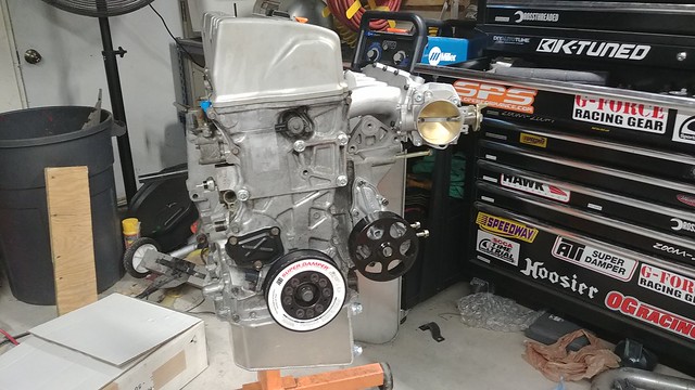
The KMiata Manifold leaves plenty of room for the adjuster, coolant and vent hoses and anything else you might want to run under the IM.


