I finally got sick of dealing with the shortcomings of the VP racing jugs and their tiny air vents, leading to it taking forever to drop a few gallons of fuel into the car. While I don’t need to do F1 pit stops or anything, some of the TT style events I’ve been running have fairly quick turn-around time between sessions (*especially* with a co-driver), and so cutting a few minutes off of that will be helpful.
So I upgraded to a pair of Hunsaker Quick-fill dump cans:
The Hunsaker jugs are a bit squatter than the VPs and so they won’t fit in the old VP fuel jug rack (something like 12-1/4″ vs 10″-ish for the VP) so a new solution needed to be made.
Time to break out the saws and scrap steel.
And the welder…
Add a couple coats of paint and call it good.
I’ve gotta say, having some light in the trailer makes a MASSIVE difference. It’s a damn sight better than working in there after hours with a drop light.
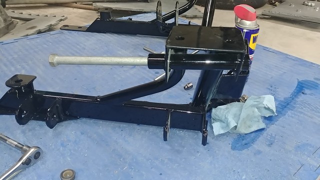
I got a dumb idea for a useful thing that I just couldn’t shake until I built the thing, so I built the damn thing. It occurred to me that having a vise in the trailer for “break it ’til it’s fixed” type work could be a useful thing to have. But I don’t have a really good place to store it, much less somewhere I’d be able to really hammer on stuff without breaking whatever it was bolted to.
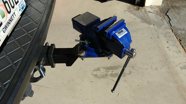
I realized that my truck weighs 6,000 lbs, tows almost 7,000 lbs regularly, and has a 2″ square hole at the back that takes readily available, cheap, off-the-shelf hitches.
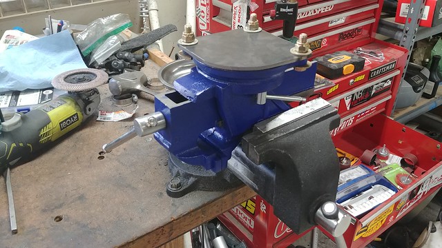
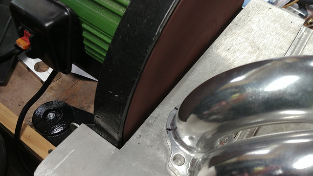
The prototype stage involved a trip to Harbor Freight. One small bench vise, one 2″ trailer hitch, and one small ATV receiver hitch to wall mount for storage.
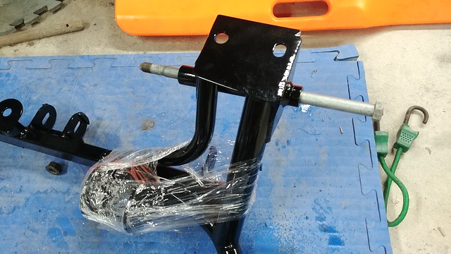
I had to cut the top (depending on which way you flip it…) corner off the ball-mount portion so it didn’t interfere with the wall when in storage:
A bit of plate, a band saw, a drill press and a disk sander gets you a nice little mount for the vise:
A little welding:
I welded a plate to the back of the ATV receiver so I’d have somewhere to drill into a wall-stud in the trailer:
It occurred to me that the D-ring on the wall mount would be a handy spot to hang a sledge hammer from. Because you always need a sledge hammer.
And finally, here it is in its ‘deployed’ configuratoin:
A quick note at the top: For this to fit you’ll really want the KMiata Intake Manifold. You MAY be able to hog enough material out of the throttle body spacer, which interferes with the alternator side spherical bearing, but the KMiata manifold has plenty of room for everything.
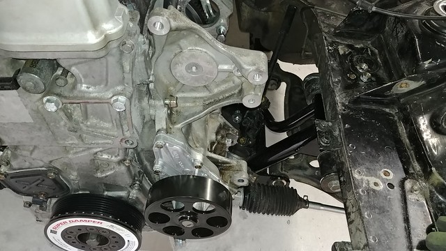
I love the simplicity of KMiata’s 4-pulley setup, but I’m not really happy with the tensioning setup. I’ve no doubt that it works, but hear me out: the K24a2 alternator bolts in with 3 bolts, perpendicular to the block. In a stock configuration, there’s a big, sprung(?) idler / tensioner pulley in the system. Since that’s gone, this setup uses washers you can see in the pictures between the alternator and water-pump housing to set the tension. Servicing any part of the accessory drive involves removing the idler pulley and, in my case, 10 washers (3 on each alternator bolt plus an additional C-shaped washer I made for the top bolt to put the last bit of tension the belt). Reassembly involves dealing with those 10 washers and putting the idler on at the same time without stripping any bolts or losing a washer.
That works fine (…ish…) if you’re doing this in a clean workshop. I can’t help but picture myself trying to fix an alternator or water pump in a wet / dirt / gravel / grass paddock space at a track or on the side of a mountain, and losing half of those parts in the dirt.
So, while I was able to get it tensioned (with the help of a pry bar and the aforementioned C-shaped washer), some more work was needed on that front. I had resigned myself at this point to simply turning up some spacers on the lathe to use instead of washers, as they’d be much easier to manage (and I could make a spare set, when it came to my attention that the Water Pump Housing from a K24z3 used a single lower bolt that runs parallel to the engine that, with some creativity, could be used as a pivot. In the stock configuration there’s a block that bolts the top of the alternator in place and it uses a sprung tensioner pulley, on the belt, but if the housing bolts up, I should be able to use that alternator and a turn-buckle style adjuster at the top to tension the belt.
Nothing’s ever that simple, however. It’s not exactly a bolt on affair.
Problem 1 is the bolt bores are different sizes / lengths. The z3 housing uses 2 long studs (vs 1 long and 2 short), and then 1 long bolt and 1 short (vs 2 long). That’s fairly minor, I just need to grab a stud and bolt. I could honestly get by with 3 bolts, but the studs help when sliding it on the first time when it’s covered in HondaBond so I don’t screw that up horribly.
This second problem is bigger, and will require a little help from my friends. The K24z3 housing is on the left, the K24a2 housing is on the right. The z3 housing uses 3 of the 4 bolt holes the same as the a2, but the one at the upper right (sharpie pointer) is in a different location. HOWEVER: The hole from the original a2 pattern is *nearly* drilled through in the z3 housing so I’ve got something to work off of.
I didn’t want to have my machinist buddy go through all the trouble of milling this thing down if the hole pattern wouldn’t line up, so I used a slightly undersized drill-bit to knock the bottom of that bore out. This way, the original bore is still there to locate an endmill off of to bore it correctly.
That top bolt is actually tight but it’s sitting on that step in the casting on the back side of the bolt. We (and by we I mean Dave) will mill in a flat for the bolt to sit flat against.
Now that I knew it fit, I could cut the big stock tensioner bracket off of the top of the pump housing and work on a turnbuckle adjustable tensioner.
After talking it over with my machinist friend, we decided to try and mount the turnbuckle adjuster to 1 of the ribs of the water pump housing. Here it is all assembled. You can see the machining in the corner for the front upper bolt, and where the turnbuckle rod end mounts.
At full retraction of the turnbuckle (to get the belt off, for example), the engine-side rod end was binding, so I turned up a 3/8″ spacer on the lathe to add some clearance, and the action’s nice and positive.
You can easily get the belt tight enough by hand, and then a quick tighten on the lock nuts secures it in place.
The KMiata Manifold leaves plenty of room for the adjuster, coolant and vent hoses and anything else you might want to run under the IM.
Thankfully for the most part, the cooling situation on these if fairly straight forward and a known quantity, though there’s *always* some custom work to be done.
First thing’s first, the hoses. The upper hose can be made from a Dayco 72277 and a Dayco 72098, with a 12″ coupler between them, and the lower is a Dayco 71718. They’ll all be need to be lightly trimmed to fit, but they’ll get you most of the way there.
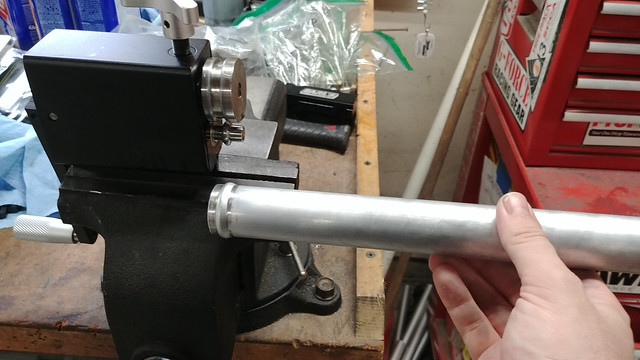
Of course, a 12″ coupler doesn’t seem to exist off the shelf, so I bought some aluminum tubing and a bead roller and got to work:
I made a strap out of a piece of tubing to secure the front of the upper radiator hose away from the front corner of the block, and the accessory belt idler pulley:
I’d been using a stock radiator for mock up so as to not risk dinging up the nice aluminum rad, but quickly found a clearance problem with the stock fan bolted on the thicker core aluminum rad, as it did not fit between the radiator and front sway bar.
With a slim-line fan ordered, I could get busy building mounts. I used the “through the core zip-tie” style ‘mounts’ it came with to secure it in place and give me something to aim at:
I cut the mounts out of steel plate. Aluminum *might* be strong enough for this (especially some CNC’d billet mounts), but this is critical enough that I’ll take the weight penalty for over-building it. I did turn up a set of spacers on the lathe out of aluminum, and the fan is bolting through weld nuts on the bottom of the mount plates
With the critical features of the lower mount done, the simpler top mount could be made:
A quick test fit shows PLENTY of room to the front sway bar:
Once all the critical fitup was done, less critical Speed Holes can be drilled:
A lick of paint and some foam-rubber insulation to seal the fan to the core, and prevent chafing:
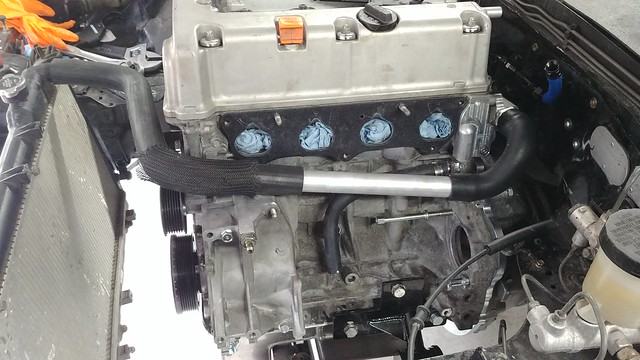
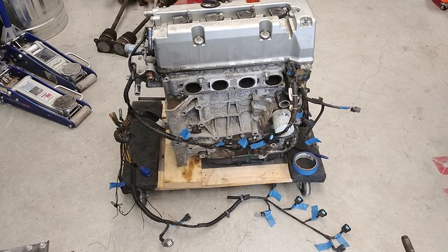
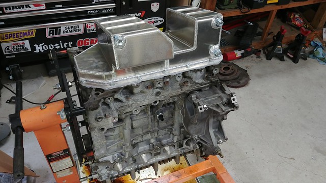
There it is, the star of the show! The Honda K24a2 from an 06-08 Acura TSX.
The first task was to strip everything unnecessary off of it. All new wiring is going in, but I’ll likely need some connectors off of the old harness, so everything gets labeled.
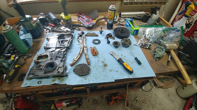
A few mods need to be made for the K-series to fit the Miata. The biggest of those is the oil pump. The a2 variant has a massive pump assembly with counter-balance shafts sitting right where the steering rack wants to live. That’s replaced with a much slimmer pump from a K20, along with a back-cover, pickup and windage tray to work specifically with the KMiata swap.
The timing cover, chains, guides and tensioners all need to come out to get at the pump. While it was already apart (and since it was 1 extra bolt to replace it), a 50-degree variable intake cam pulley from the RSX Type-S took the place of the 25-degree sweep unit from the TSX.
Leak testing the pan before it goes on.
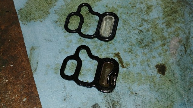
A new gasket & seals set from Honda went in to replace anything worn. The O-rings around the oil system and for the VTEC solenoids were notable in being seriously perished.
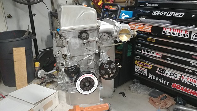
That done, the front of the engine could go back together. Timing chain, guides, tensioner, timing cover, water pump and housing:
Because I’m using the ATI damper, which is smaller than the stock harmonic balancer, I ended up needing to go with a shorter belt (a 6PK1035, if anyone reading this decides they need to go in a similar direction):
I love the simplicity of KMiata’s 4-pulley setup, but I’m not really happy with the tensioning setup. As this post is long enough, I’ll dedicate a separate post to that adventure. I’ve no doubt that it works, but I can’t help but picture myself trying to fix an alternator or water pump in a wet / dirt . gravel / grass paddock space at a track or on the side of a mountain, and losing half of those parts in the dirt.
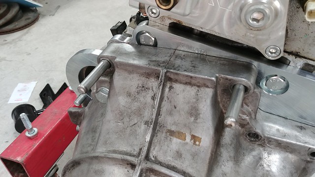
You’ll notice at some point here the engine was installed. That was a HUGE morale booster. There wasn’t much super interesting with that, it slid right in, however I do want to share a tip that’s been passed down to me from others that I found super useful: Making dowels to line up the transmission and engine.
That made getting the transmission on SO much easier.
Another quirk of the KMiata swap is that the starter is on the “wrong” side of the engine relative to the Miata’s, so the transmission bellhousing needs to be clearanced for it to fit:
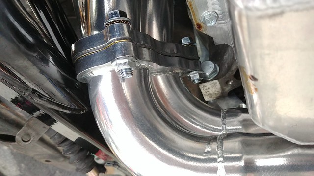
Next up was to start making and test-fitting cooling system parts. The lower radiator hose (a stock S2000 lower hose) was fairly straight forward:
The upper hose seems to need to be 3 pieces. I’m still on the hunt for a single hose solution, but for now, it looks like a 72277 and a 72098 hose with a long coupler need to be used.
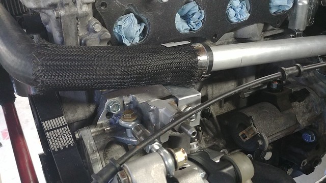
A 1 foot length of aluminum tube seemed to be just about perfect. A couple of passes run on the bead-roller made a nice looking piece:
I’m going to put some more anti-abrasion sleeve and a bit of retention where it wraps around the front of the engine, because while it doesn’t touch while not loaded, I imagine when it’s full of water and moving with the car & engine, it’ll definitely rub there. Worst case it’s easy / cheap insurance that I’m not wetting down the course / track.
Yes that’s a stock radiator. No, it won’t be in the final setup. I’m using it for mockup now to avoid dinging up the shiny aluminum one while still building this setup.
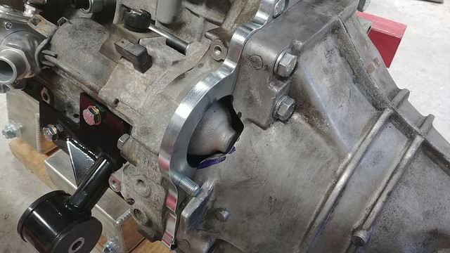
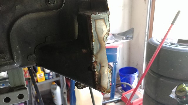
On to the other side of the motor, I can mock up the exhaust manifold. It is on the ‘wrong’ side of the engine (compared to the stock Miata configuration), so it has a crossover tube that bolts on that runs between the bell housing and oil pan.
Unfortunately here I run into another V8Roadsters subframe issue. The crossover pipe runs into the hoop that connects both sides of the subframe and runs under the engine.
So now I have the pleasure of taking a freshly ceramic coated to the grinder to gain a couple millimeters of clearance. Which is nice…
So now it clears, but…ugh.
At least it won’t affect performance, or rattle every time I come off throttle.
It’s time. It’s finally here. With the Chasing the Dragon Hill Climb complete (and successful beyond my wildest dreams, making the fastest pass by a Miata ever), it’s time to put the bigger, lighter Honda motor in the race car.
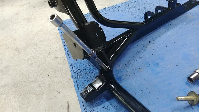
Unfortunately however, things got off to a rocky start. Prior to the Hill Climb I started test fitting things to the V8Roadsters subframe and all was not well.
The first bit of prep was to get the steering rack on the subframe. So as to not lose the NB rack bolts I figured I’d put the bolts into the threaded holes in the subframe for safe keeping. 3 out of 4 had powder coat completely boogering the bolt holes. Adding to the fun, the thread pitch of those holes is M12x1.25mm, which is the one M12 tap I don’t actually have in stock. A quick Amazon shopping trip and a couple days later, the tap comes in. After chasing the threads in the good bolt hole and 2 of the 3 bad ones, I realize 1 of the engine mount brackets completely blocks access to the 4th. Improvise and overcome right?
Turns out, a 5/16″ 12-point socket makes a good-enough narrow access tap wrench for an M12 tap.
That’s not great, but a pretty small issue all things considered. Then a friend (thanks Nick!) who has experience with V8R subframes suggested I check the rest of the holes, and that’s when the big problems started. I could not get the upper control arm bolts through the bores at all.
I went as far as creating a custom tool with some rod and sand paper to grind the powdercoat out of the bores, thinking it was a similar issue to the steering rack bolts, but no, the bore was shaped like a banana. I still don’t know if it was overheated when it was welded to the frame or what, but it wasn’t great. And given that it left the shop like that, their QC wasn’t exactly giving me warm-fuzzies either.
To KMiata’s credit, they handled getting a new one shipped out and return shipping for the bad one to V8Roadsters to ‘investigate’. Once we determined just how bad the problem was, I had a new one in hand a few days later.
And check it out: bolts that go in without any hammering or clearance! What a concept!
Next it was time to get the steering rack prepared. Because of tight clearance to the oil pan (…a recurring theme…), all the hydraulic fittings on the steering rack housing had to be cut off. I used a 3/16″ rivet and some JBweld to seal the holes.
Next I discovered that Mazda changed the design of their inner tie rod lock washers. The old style washers sat on the OD of the tie rod’s threads, so it was flat between the rack and the tie rod. The newer style lock washers have a shoulder that goes on the over OD of the rack. That prevents my steering rack limiters from seating all the way at the ends of the rack, taking another 3/8″ or so of travel out of the rack.
I corrected that by throwing the limiters in the lathe to put a counter-bore in the ID to clear the washer on 1 side, but still ride nice and snug on the rack:
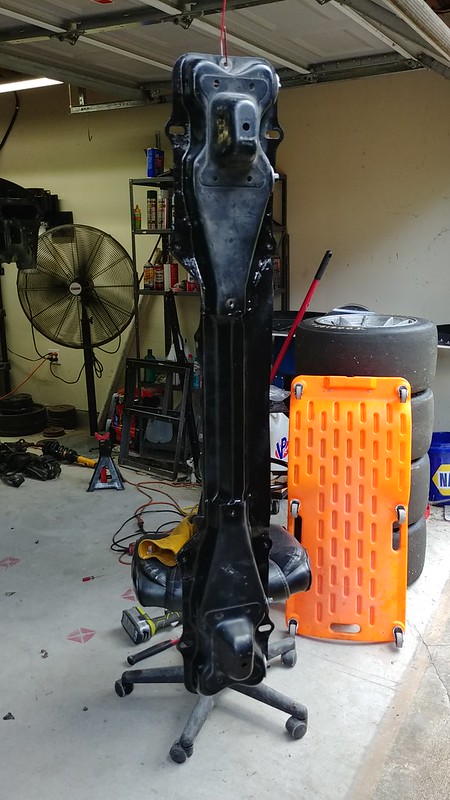
Time to start disassembling the car:
Given that I’m going to have to install and pull the drivetrain several times over the course of the coming build, I also wanted to remove the upper radiator support (which doesn’t actually support the radiator in an NA Miata), and make the front bumper bar into a bolt-on piece. As you can see, the engine and transmission will come out of the car practically straight:
A little bit of cutting and welding later, and the front bar bolts to the chassis legs:
It’s so much easier pulling the whole thing as a unit:
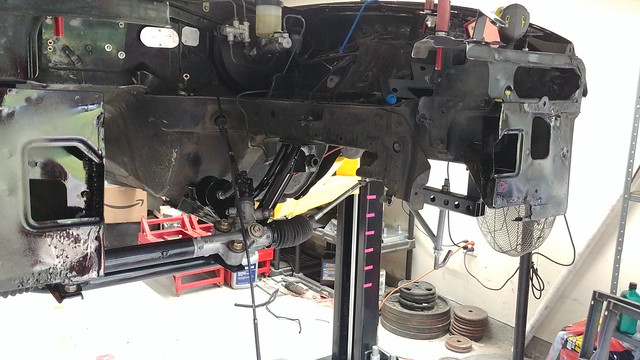
With the rack put back together, I could finally put the subframe in the car. Unfortunately there’s evidence that my car has been in a minor front-ender, which appears to have slightly tweaked the subframe pickup points. Because of that, I had to pat my head and rub my tummy and figure out which order the bolts wanted to go in so that all the holes actually lined up, but once I figured out which hole was the furthest out and started there, it all bolted in.
I found a couple of bad ball joints during disassembly, so I called Mazda Motorsports and re-loaded the parts cannon to get good parts on board, but once that was done, everything bolted up nice and easy (including the steering rack)
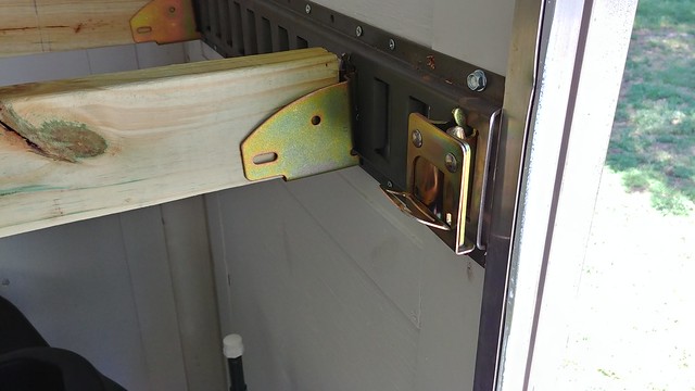
The first outing with the trailer went well, but I really wasn’t happy with the new D Rings. Or at least, with how they were secured to the trailer.
They have fairly large backing plates, but at the end of the day, they’re still just secured to plywood.
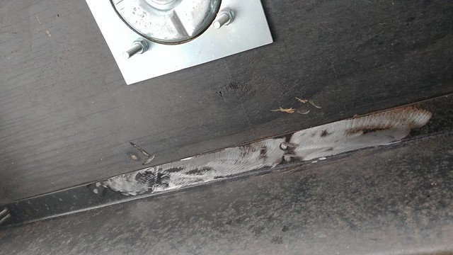
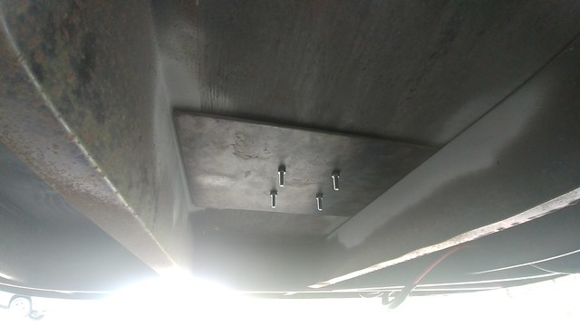
Cinching the car with ratchet strap induced a visible bow in the floor, and didn’t exactly give me that warm-fuzzy feeling about its ability to hold the car in place. More drastic measures needed to be taken in the form of a pair of 12″ x 15″, 3/16″ thick steel plates to be welded to the frame of the trailer.
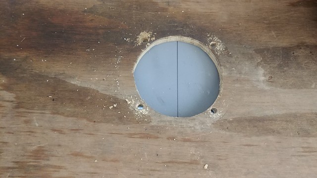
The first job was to cut off a handful of floor screws that were hanging right in the way, because of course they were (see photo above).
I had to grind a bunch of paint and surface rust off so I have something decent to weld to:
Because I wouldn’t be able to get at much of that steel after welding, I hit the trailer frame and the tops of the backing plates with a coat of weld-thru primer:
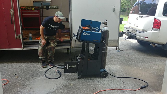
The next day, both the trailer and the welder got dragged up the hill. I’ve never had the occasion to use the 110v plug adapter for the welder, but it did just fine. I’m honestly surprised I didn’t blow the garage circuit breaker.
It was a multi-step process of figuring out where they needed to be (the frame is made of Z channel, so 1 side I had to be right against the frame rail, and the other I had a couple inches of flat steel to play with. A buddy helped me get them more or less centered from above, then we popped a pair of transfer punch marks on the plate. Drilled those, took it back up and bolted it to the floor to confirm alignment, then back to the shop to drill the other 2 holes. Rinse and repeat. But once that was done, the floor supported the plates for welding, which made that part significantly simpler.
The view from above, centering line definitely close enough.
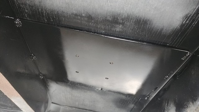
Without a doubt these aren’t the prettiest welds I’ve ever made, but they’ll do the job.
The finished product looks exactly the same from top-side, but I feel a LOT better tying a car to these now.
And because nothing’s ever simple: I had put down the rear ‘RV leveling’ jacks to stabilize the trailer as I unhitched it from the tow pig prior to welding. When I retracted them after we got done, 1 of them went up fine, while the other one just unthreaded the jack-screw, which shouldn’t be possible in normal operation. I the jack off the trailer and disassembled it in the shop and found that a roll pin that secures the inner washer (to prevent it from just unthreading) had sheared off. A quick trip to Ace got that sorted out for about $0.35 (and a lot of cussing)
My lathe doesn’t have a Digital Read Out (DRO). This isn’t an issue on a high quality machine because the hand-wheel increments are accurate. Well, on a cheap lathe, they’re merely suggestions at best. At worst, a quick way to scrap parts.
Given that, I’ve been thinking for an age on how to go about making accurate measurements on the lathe itself.
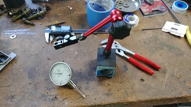
Carriage travel is fairly straight forward: A 2″ dial indicator on a magnetic base, plonk it down on the ways perpendicular to the carriage.
The hard part is the cross-feed. Bigger lathes have plenty of places to put magnetic bases, but real estate is pretty sparse on this one. There’s plenty of space on the cross-slide itself, but that is what I need to measure, so it’s a non starter.
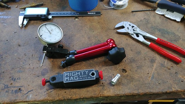
Finally, I found the solution. A Mighty Mag base. It’s a strong magnet, with a very narrow footprint. With that, I can steal the arm & indicator holder from a Noga-style indicator base, make an adapter(on the lathe!) to connect the 2, and that would allow me to affix the indicator to the carriage, and indicate the amount of travel in / out.
I wipped up the adapter:
I used the drill press to drill a 3/16″ hole about half way into the shank to give the pinch bolt something to bite into and secure it… securely… into the mag mount:
The parts, laid out for assembly.
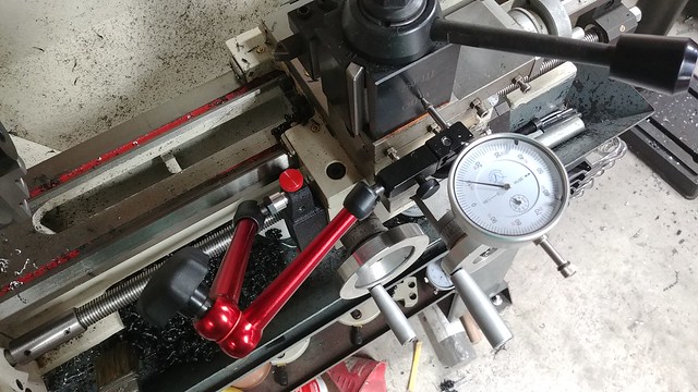
And finally, on the lathe. The left side of the carriage is about the only spot I could reasonably put it where it wouldn’t interfere with the hand-wheels or power-feed controls and be bumped around. Almost as though it’s made to go there:
Boom. Analog Read Out (ARO? Is that a thing? It is now…) complete!
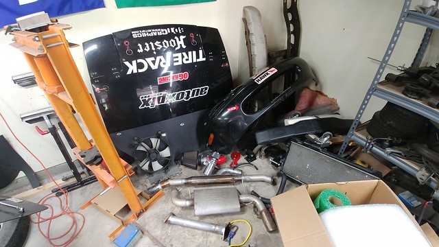
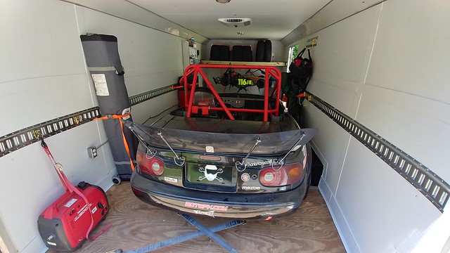
The main idea is the keep things off of the floor, because, well…gravity doesn’t make a good load binder. In addition to a boatload of E Track, I will put a small cabinet / bench to put on a wall, a spot for my tool box, a fuel jug carrier, and a tire rack with a way to tie the tires down.
I built the tire rack using 4 E Track 2×4 pockets, a couple 2x4s, and some bracing between the 2. It’ll take 4 race tires and 2 trailer spares. I’m using single-slot E Track anchors to secure the tires. The fuel jug rack is also there in front of the kart:
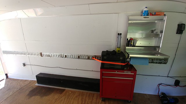
I also put up, just, a BUNCH of E Track. Along both sides (at a useful height this time, if you compare to to earlier photos, it was barely higher than the inner fenders).
I also put some at the very front of the trailer to serve as a bumper for the kart, to keep it from rubbing against the wall, but also to serve as storage when the Kart isn’t there:
And then loaded everything up 1 more time as a final test to make sure I have room for everything where I think it ought to go, and as a systems test of the winch and pulley block, as I hadn’t actually pulled anything up with it yet.
Plenty clearance for the toolbox on the driver’s side:
And space on the passenger side as well. That fender’s a nice place to hang that folding table:
Canopy and generator added at the rear, with plenty of room for other sundries:
A handy dandy E Track fire extinguisher mount, and a couple of E Track D-ring straps make a great way to store folding chairs:
Even with the car, kart, toolbox and cooler loaded up, there’s plenty of room for more stuff should the need arise.
And finally, the all important bottle opener by the door. Can’t go without that.
Looks like we’re ready to go for her maiden voyage this weekend 😀
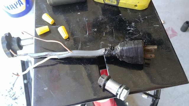
As previously discussed, the shore power connection wasn’t exactly high quality. Someone removed the 30 Amp plug and replaced it with a 15 Amp plug that didn’t actually fit in the housing. Since it was on the driver’s side, going down the road every time I looked in the mirror, that thing was flapping at me.
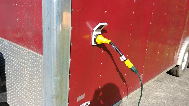
Since everything had to come off the wall for paint, including the electrical panel, the was a fairly straight forward fix. A new 30A shore power connector was fitted, along with an adapter for use with normal 20A service.
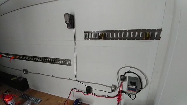
With that fixed, it was a simple matter of relocating the wiring in a way that was tidier, and positioned in a better place (the plugs were too high on the wall originally, and the E Track too low, so they switched positions). I removed the plug along the front wall, as it seemed superflous. I may re-add that later, but I already have plenty of 120v plugs in the trailer now.
With the 120v service sorted it, it was time to move to the 12v side of things. My main 12v goals are: -A winch to load the car -An electrical jack -A battery to power all that (and eventually some interior lights) -A solar panel to keep the battery charged
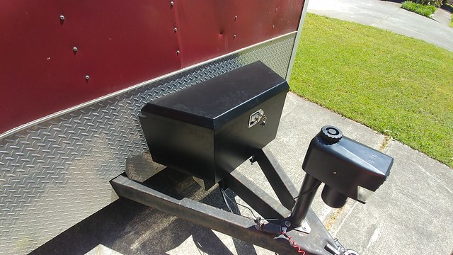
The main component here is the battery and battery box. A tongue tool box from HF was mounted at the front of the trailer.
I didn’t realize when I bought it that it was narrower than the outer frame rails, but I figured it was cheap, and it was big enough to do what I needed, so while it might look weird, there’s no real reason to replace it at this point.
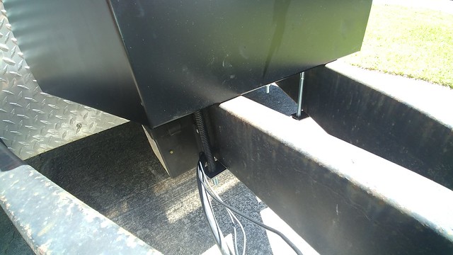
I was a little concerned with the front mount bolts chafing the wiring harness from the truck:
I found that I didn’t have any wire loom big enough to wrap around all those cables, but I DID have loom big enough to fit around the bolt. Stupid? Stupid like a fox!
The battery box was mounted around the center frame rail:
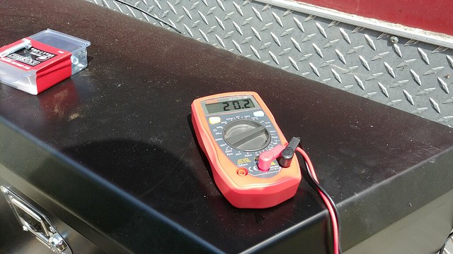
I didn’t have much horizontal real-estate to mount the solar panel to, but when parked at home, the panel faces nearly due west, and is in full sun in the afternoon.
I was a bit concerned it wouldn’t work well like that (since all directions are to mount it horizontally), but it appears to be putting out plenty of juice:
The battery never sees that much power, thankfully, as the solar panel runs through a 12v charge controller to prevent over charging the battery.
I drilled a few holes through the frame with big rubber grommets for the 12v wires to pass from the battery to inside the trailer under the floor, with marine cable pass-throughs to keep the weather and bugs out.
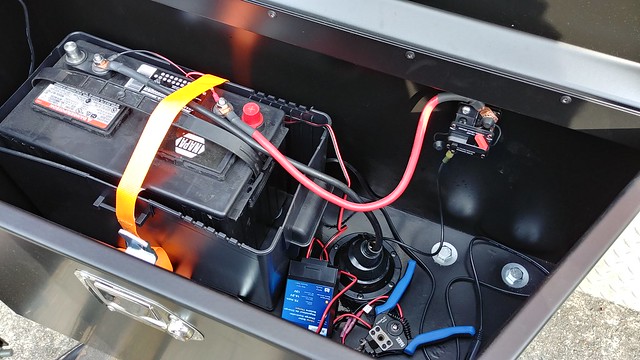
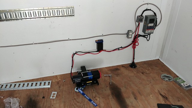
I mounted the winch using a Bulldog winch mount. The front 2 bolts are through the frame, the rear 2 are bolted through a 6 x 8″, 3/8″ thick spreader plate.
The winch wiring runs to the solenoid / wireless control box, and then to a 12v fuse block to provide service for lights and other sundries, then to the battery via a 150A circuit breaker.
It’s definitely not a professional job (because I’m definitely not a professional), but it’s about probably the tidiest I could do without shortening the winch power cables. That’ll probably happen eventually, but I want to wait for a few months and make sure nothing crops up as a reason to move something drastically.
The electrics are *DONE*. FINALLY. Between drilling holes for grommets through the frame, making cables and figuring out where I want everything mounted, and cleaning up the 120v wiring, it took all my free time for about 3 days.
Oh! Wait…I’m sick or walking all the way to the shop for fresh tool batteries. I’ve got an idea!


