Splitter Leading Edge Reinforcement

So far I’ve been loving the new splitter, however because of the nature of the DiBond, the leading edge is a bit soft and has taken a few licks. I borrowed an idea from a couple people in other classes, and put a reinforcement / trim strip along the leading edge of the splitter.

Lowes sells aluminum channel to “trim” 1/4″ ply (which happens to be the same size as the dibond my & their splitters are made of)
This will make the leading edge much less of a wear surface. Bending and pie-cutting this stuff in a way that doesn’t cause stress fractures, and slotting it to clear the mounts is a royal pain, but it will add a ton of longevity.

20170328_232934
I reinforced both the front and rear edges. The front is to protect the leading edge of the Dibond. The spar across the rear is to add a little more rigidity along the ‘long’ side of the splitter.

20170404_180823

20170404_181236

The fact that it looks a little Mad Max-ish doesn’t hurt either 😀

Aero: Front Splitter V2.0

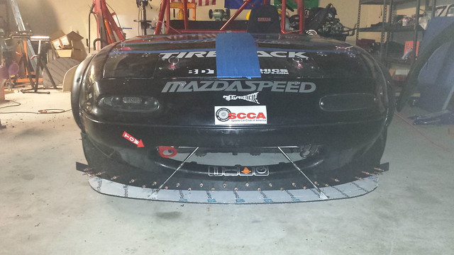
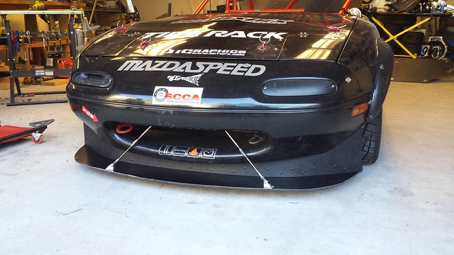
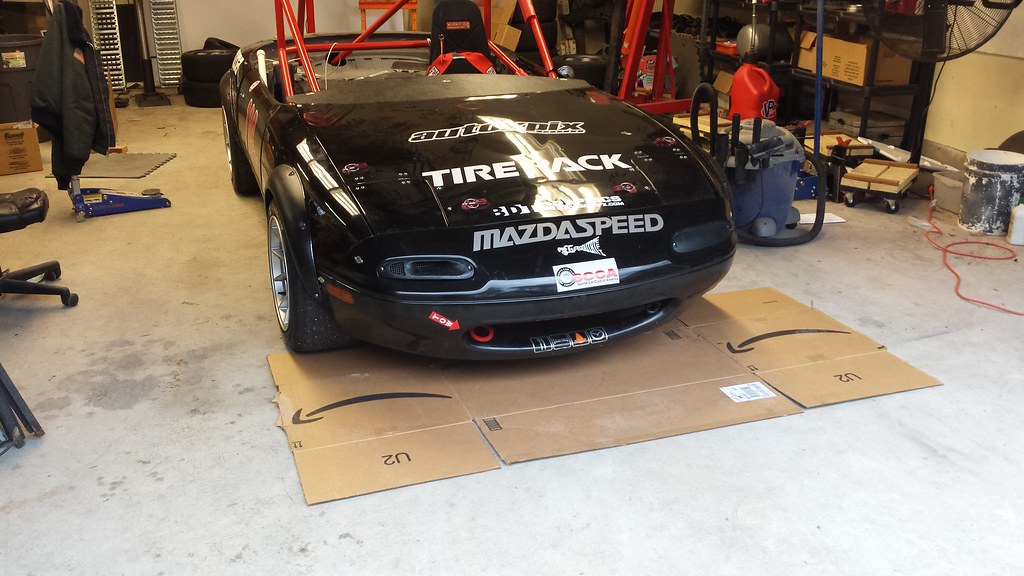
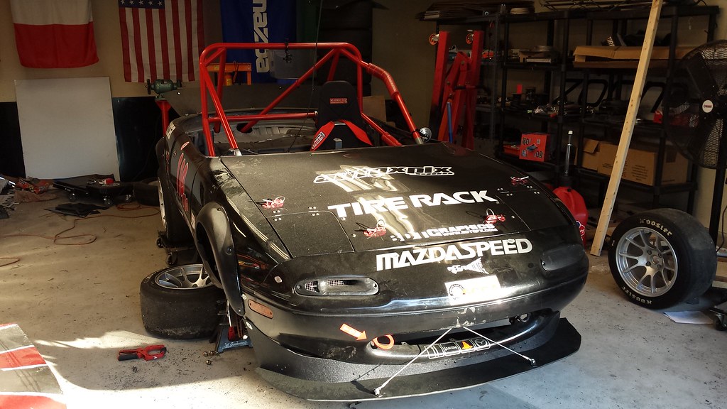
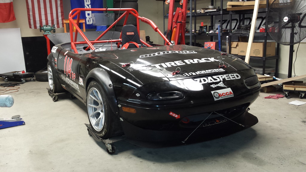
After last season, Splitter V1.0 was seriously trashed. Placed on a flat surface, there was almost 2″ of bend across its width, so at a minimum I had to replace what was there. At a maximum, it was time for a complete rethink.

It was definitely time for a complete rethink.

So, based on what I’d learned making and repairing the first one, I set about replacing every single component save the 2 quick release pins. I didn’t intend for it to be that thorough of a redesign, but during the offseason, if there’s opportunity for improvement “while I’m in there,” you might as well take advantage of that.


Part 1: The Rear Chassis
Mounts

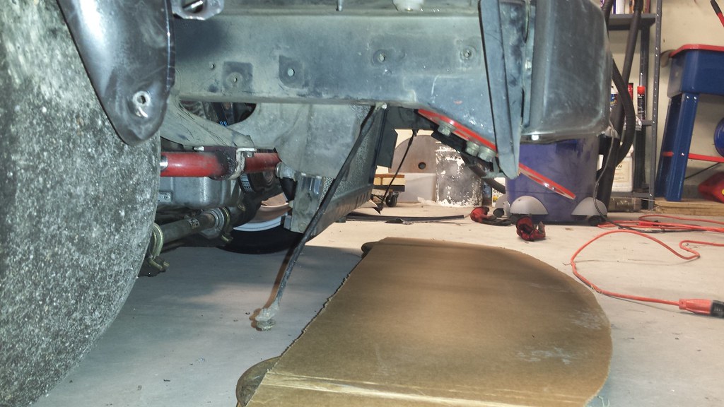
These were the pieces I had far and away the most trouble with last season. They were not adjustable, so once I eyeballed the height the 1st time, that’s where they lived. Furthermore they were difficult from a maintenance perspective, a once you hit something hard enough to bend them, the only thing to do was attempt to beat them straight with a hammer, or completely re-build them. There had to be a better way.

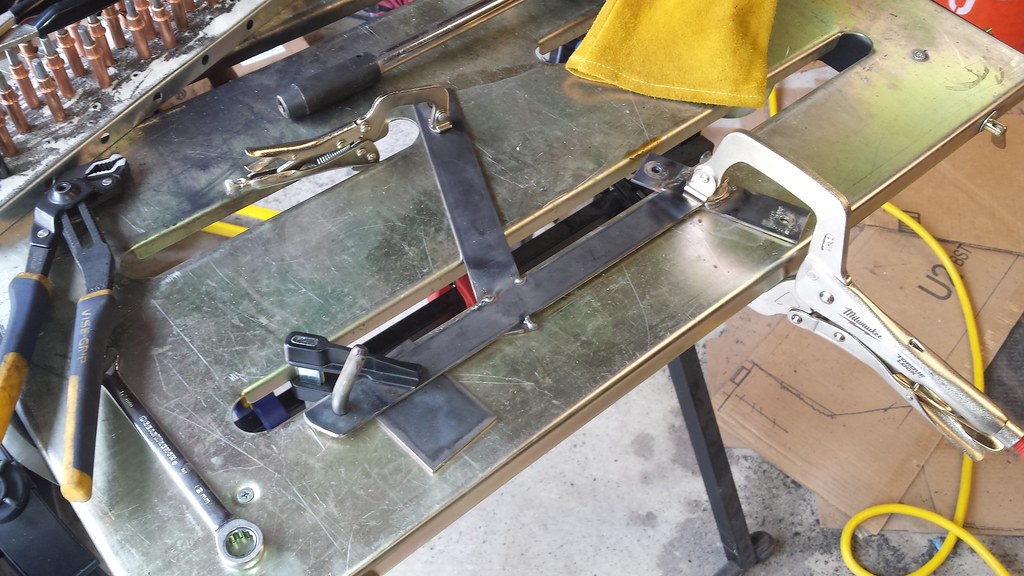
This piece took a bit of evolutionary engineering, but I think the result will be up to the task. You can see V1.0 on the left, bent in a couple different directions, and very unwilling to be bent back straight (especially along the longer edge).

20161111_140926


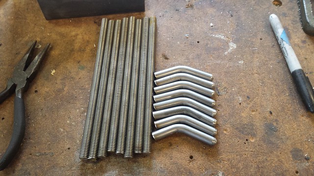
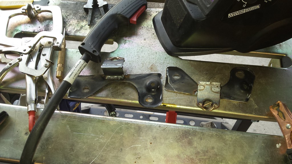
Instead of having a single piece mount, I decided to make a very strong mount to the chassis, with weaker sacrificial hooks to take the brunt of any larger impacts. The hooks are very easy to remove & replace, and to manufacture. The hooks are simply a length of 3/8″ threaded rod, and a short bent piece of steel round bar.

20170116_135941


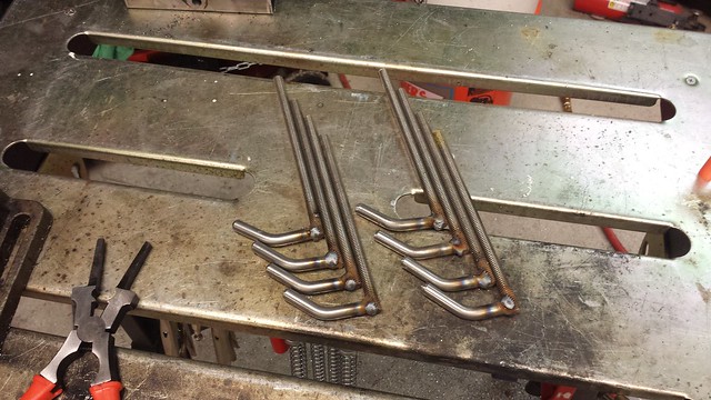
A quick bit of welding and I have (what I hope to be…) a season’s worth of replacement. Hopefully more.

20170116_202426


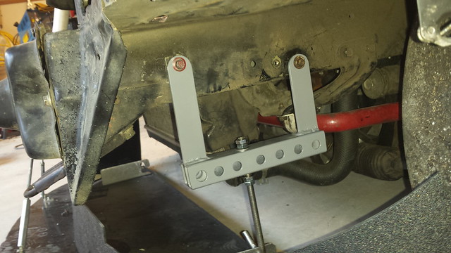
After a bit of time on the drill press and a coat of Machine Grey, and the chassis mounts are done.

20161124_161043


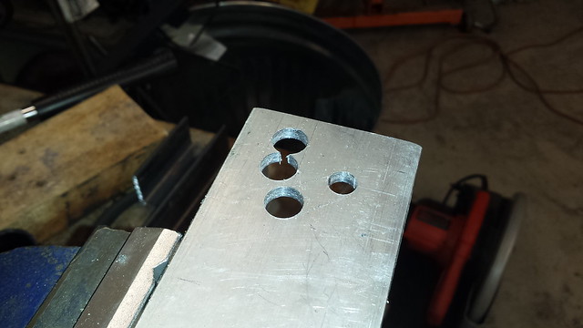
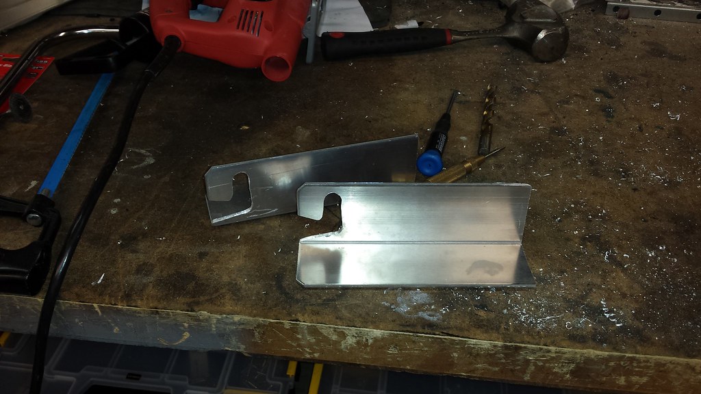
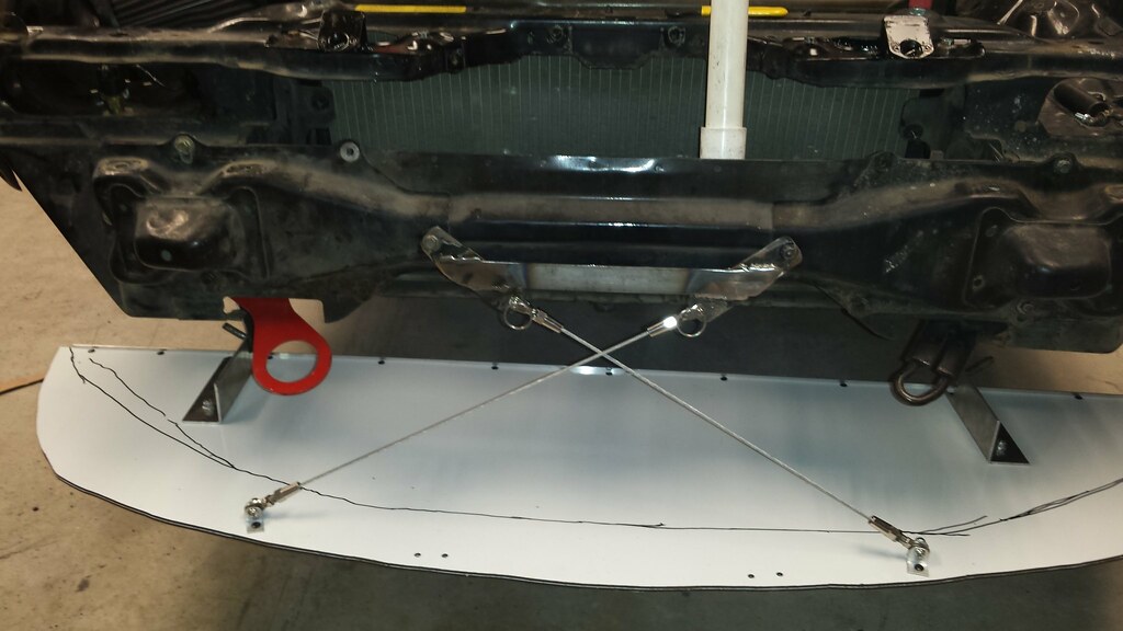
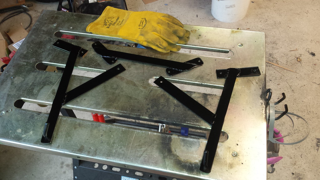
Part 2: The Rear Splitter Mounts

The Hooks on the splitter that held it onto the chassis mounts also took a beating last year. Also, their geometry meant that with a good bit of load on the front, the rear hooks would lift off of the mounts. Unlikely to happen under real world conditions, but also suboptimal.

Given that, I went with stronger material (1/4″ Aluminum, up from 1/8″), and a more angled hook design that keeps it located both horizontally and vertically.

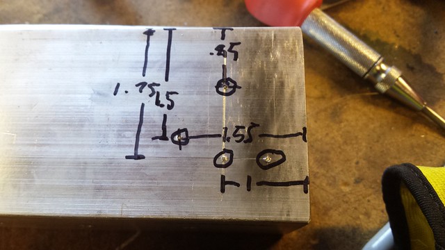
After a bit of figuring, this was the design I came up with. The bottom 3 holes are 1/2″, and the top one 3/8″ to tightly hold onto the chassis mounts.

20170107_134517

20170107_155441


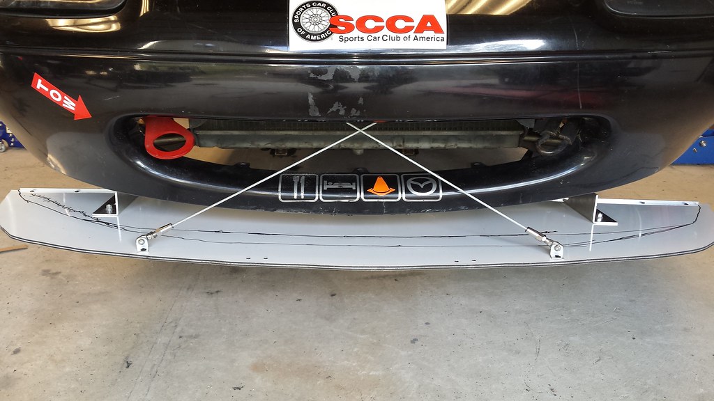
After a bit of cleanup and fitment testing, these are complete:

20170107_164751


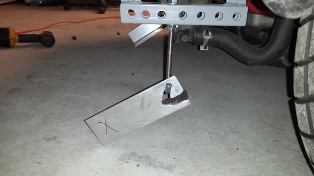
Part 3: The Front Chassis Mounts

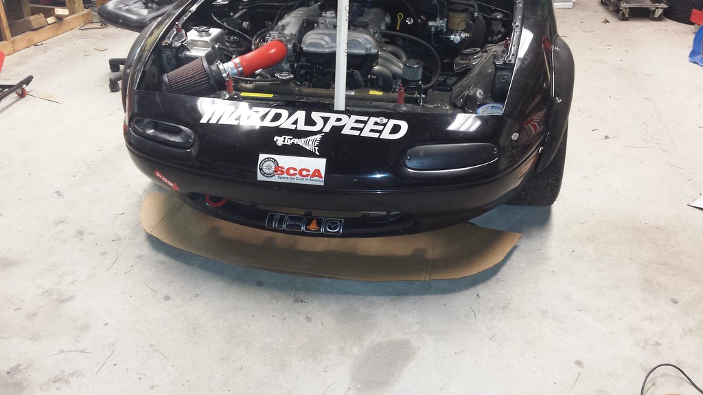
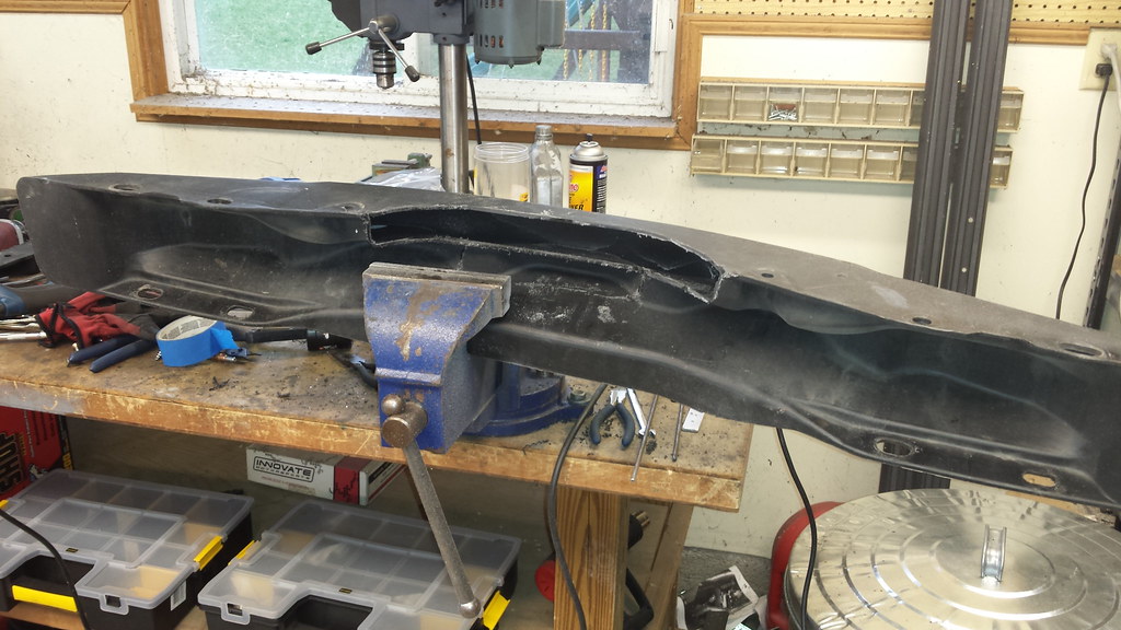
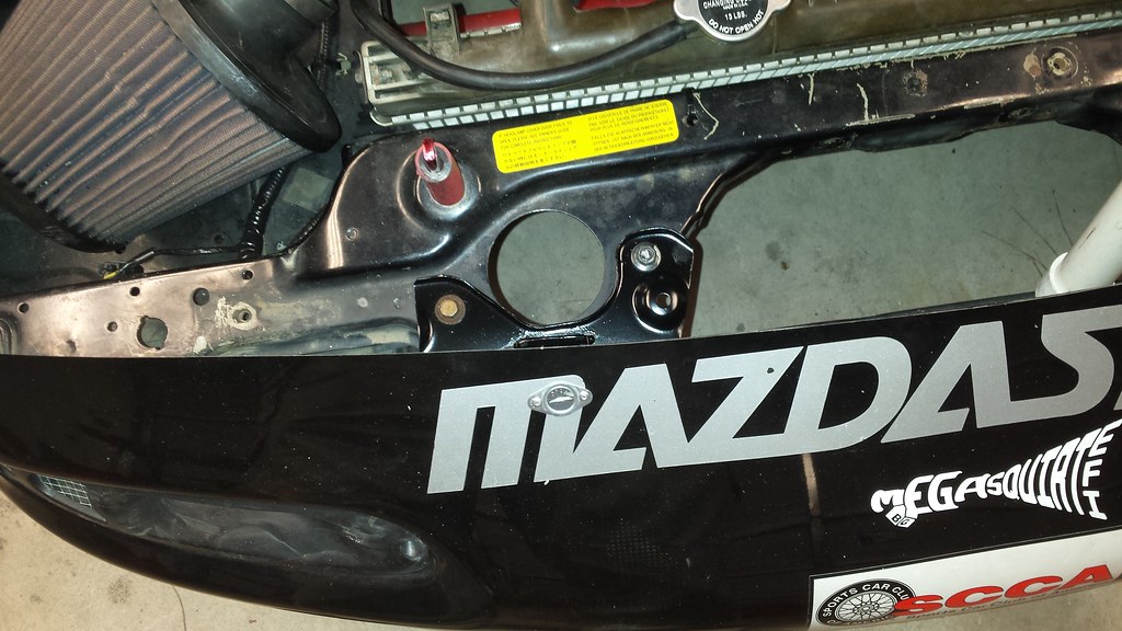
The front chassis mount (under the front bumper) has always been a pain. It allowed for no deflection (which meant bent front splitter struts), and because they only had 1/4″ holes for the quick-release pins, they were very finicky to get everything lined up with.

Inspiration from this came from a relatively prestigious place: The Dodge Viper ACR. I noticed that it had a mount that’s basically only rigid when downward load is put on it (ie: aerodynamic load), but would allow for upward deflection (ie: for off course excursions) to prevent the struts from taking all of that strain.

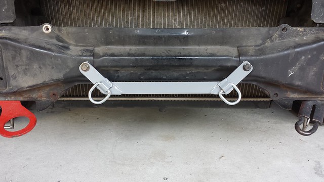
Here’s what I came up with. The D-rings are completely rigid in tension (ie: aero load), but will allow for deflection (ie: bigger cone strikes or bottoming) to hopefully prevent bending the struts. As an additional bonus, the target I’ll need to hit in order to mount the quick release pins is orders of magnitude larger, which will make mounting the splitter at the track far easier.

20170115_120636


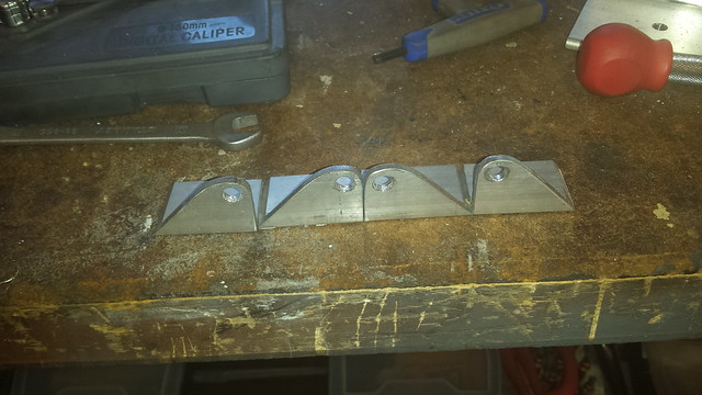
Part 4: The Front Splitter Mounts & Struts

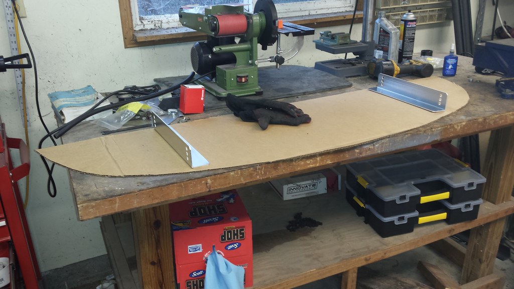
The front splitter mounts did the job, but were a little small in surface area against the splitter. They were also short legs, meaning that the nuts for where it bolts to the splitter and where it bolts to the struts were practically on top of each other. I used the miter-saw I received as a Christmas gift to throw these together (shown with a spare set):

20170109_140953


I also found some turn-buckle rigging forks on Amazon that, with a little bit of drilling and welding, I was able to make into a pair of new front struts.


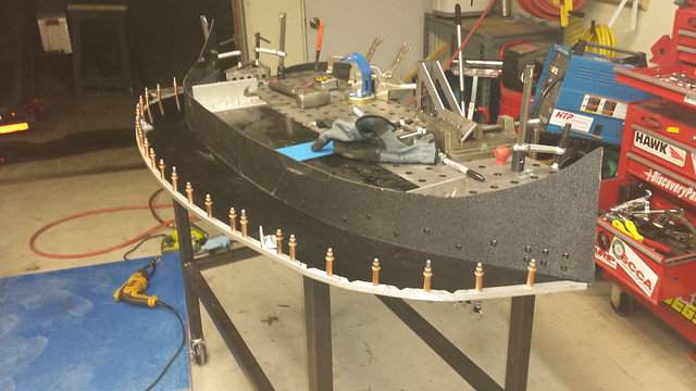
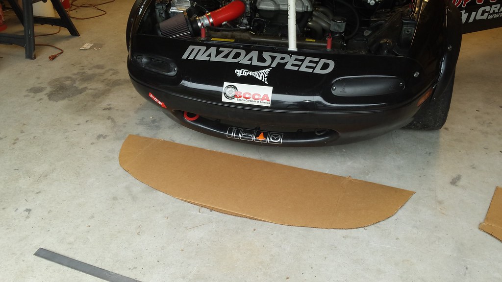
Part 5: The Splitter and Final Assembly

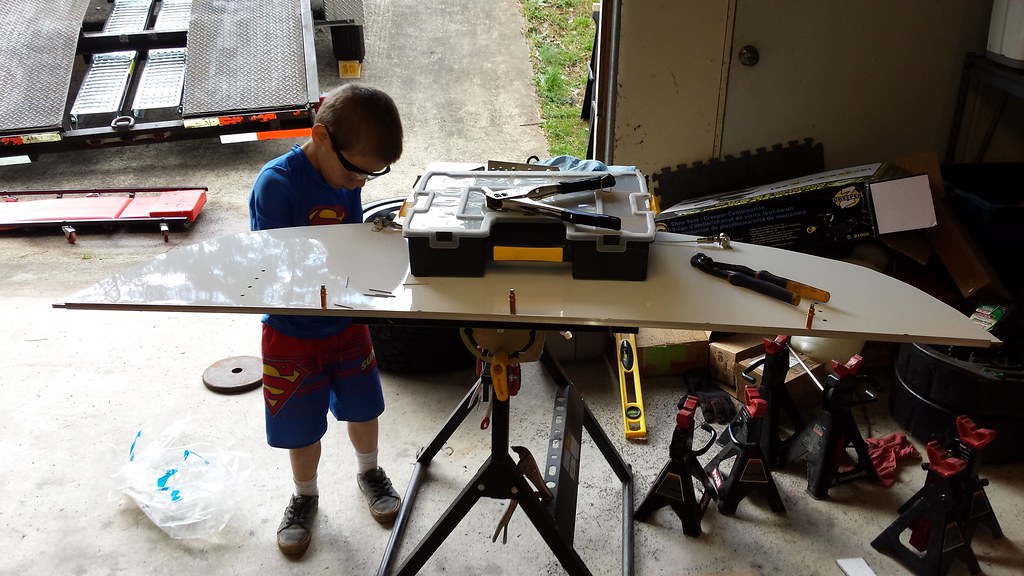
Finally, we get to the splitter itself. Using the laminated sheets of DiBond ended up being both a ton of work, and fairly ineffective. After the rigors of the season, the bottom sheet was fairly worn down (another casualty of non-adjustable rear mounts) and it never was as stiff as I would like.

After consulting with some buddies who know more about this stuff than I, I decided to go with 1/4″ Dibond. The single 1/4″ sheet is far sturdier than the laminated 1/8″ sheets.

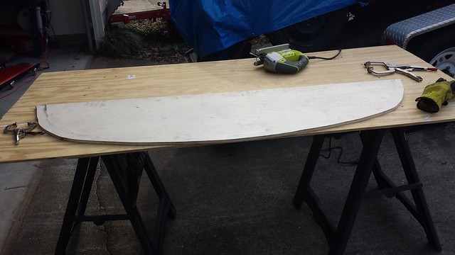
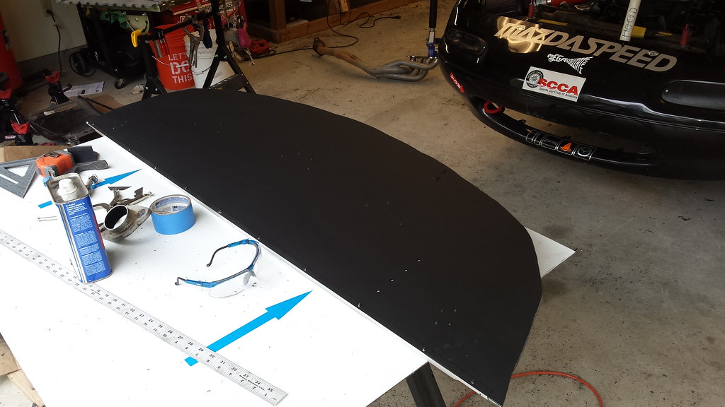
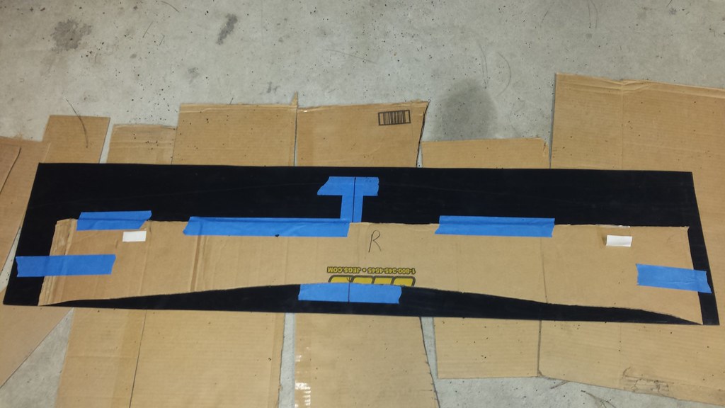
The first step was to make cleaner (and thicker) buck for the splitter. The lines on the 1st one weren’t all that clean. This will make for fairly quick & easy replication with a router & a flush-trim router bit.

20170117_152031


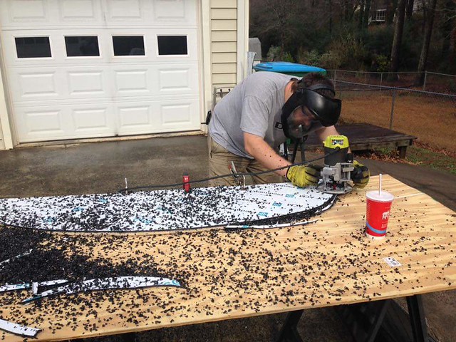
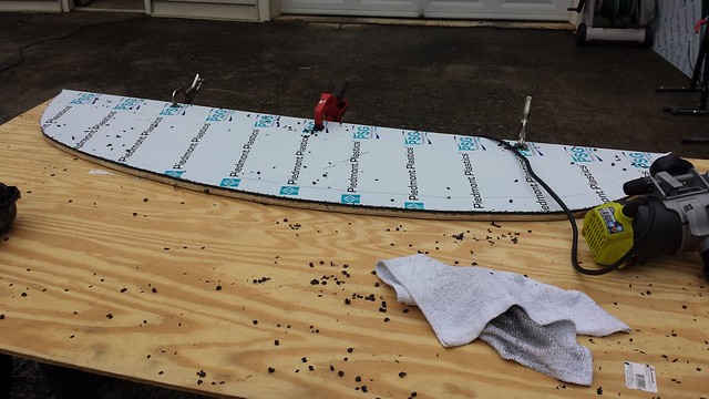
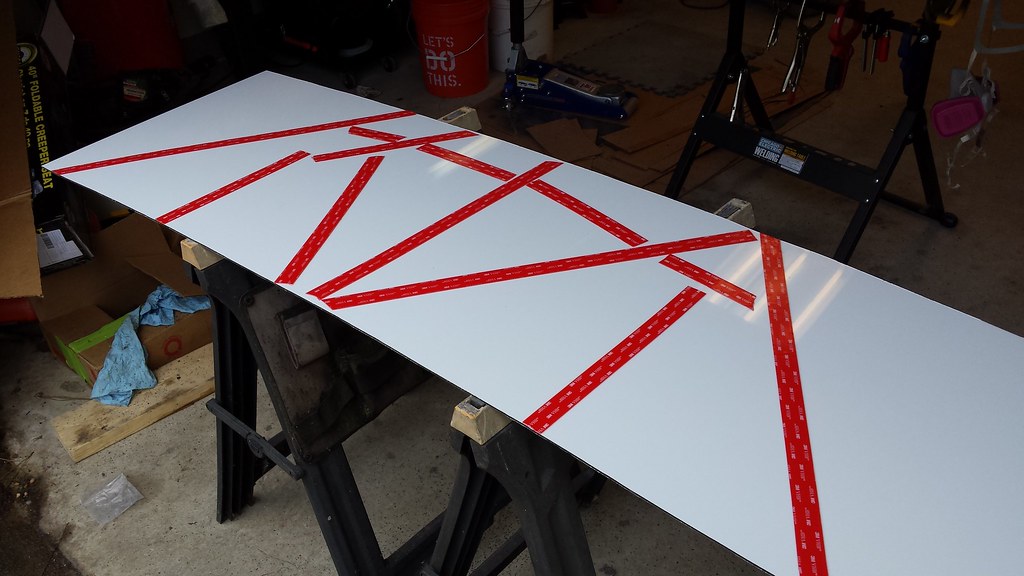
I picked up a brand spankin’ new sheet of 1/4″ Dibond, and we managed to cut 3 splitter blanks out of it, then trimmed them down with the router. It’s a super dirty process, but it is super effective.

FB_IMG_1485110592446

20170121_150148


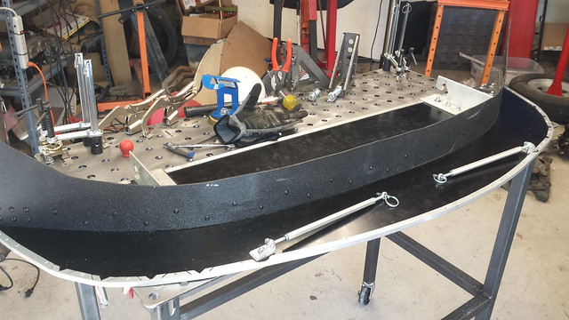
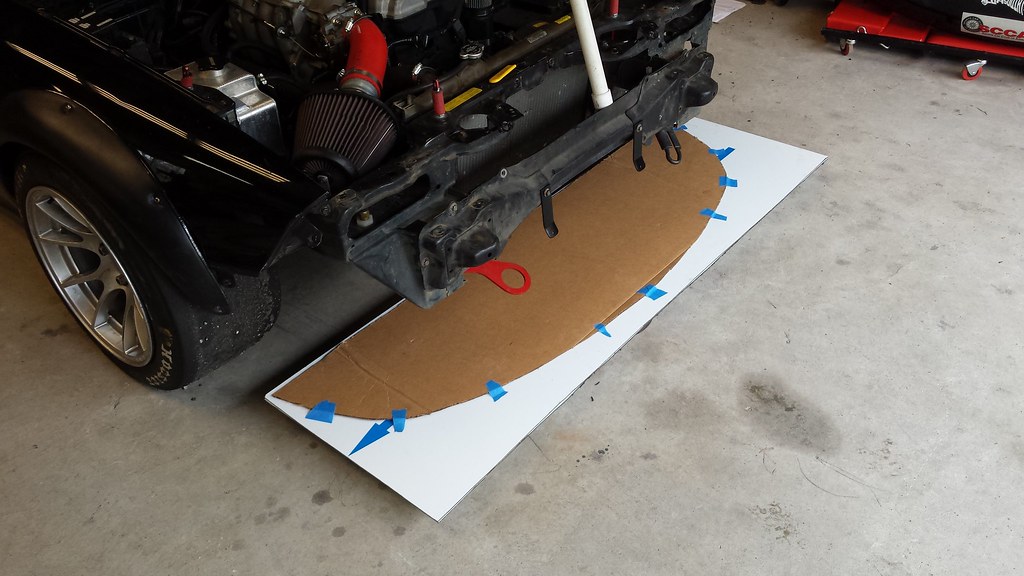
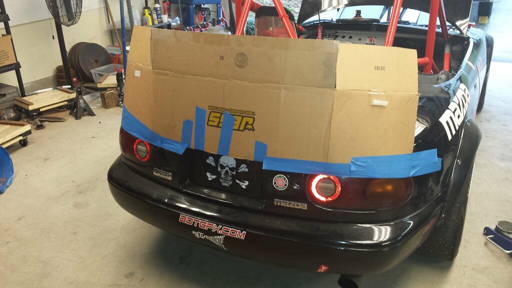
Instead of using sections of the Home Depot Racing Supply paver edging for the air dam, I went ahead and used the whole one (so it would be more rigid), then we riveted the original air-dam to it to use for mock up, to then make a pattern (and buck) for a new design:

20170127_112707

20170121_182454


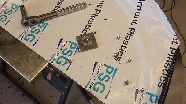
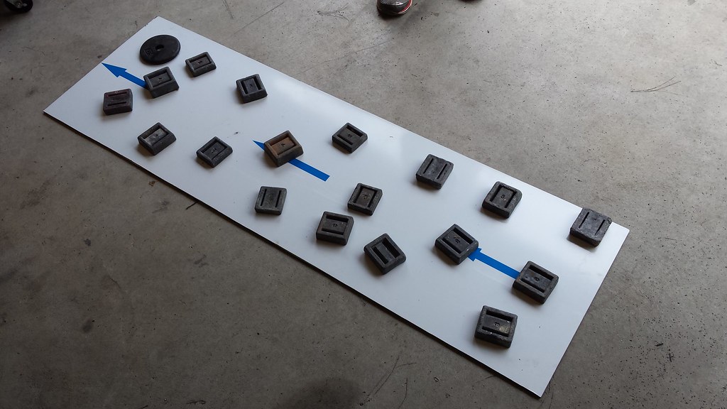
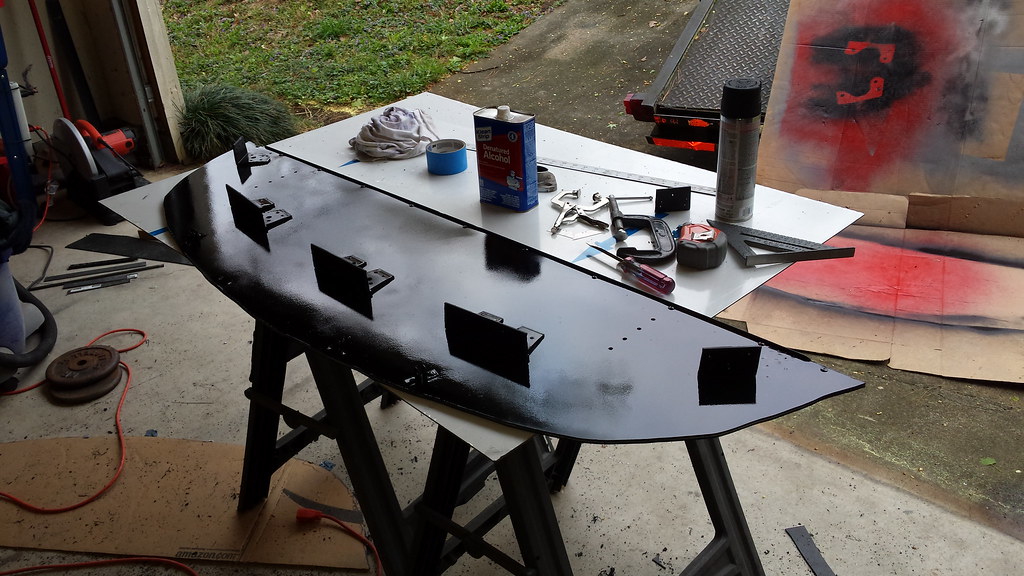
Once all the mock-up was done, it was time to disassemble the whole thing and put the “real” parts on. All of the parts were mounted using elevator bolts.

I made a spacer to use with a nut and a washer stack to pull each elevator bolt into place:

20170127_103449


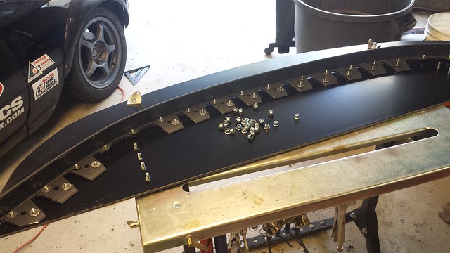
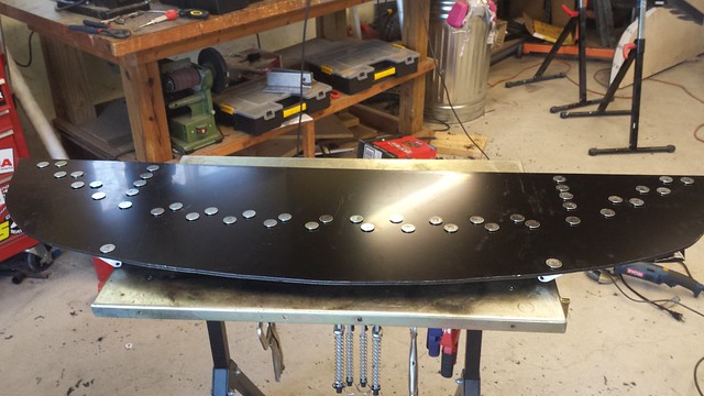
After a bit of sweat equity, this is what the bottom looks like. The nice thing is that they have very thick bases, which allows them to serve as something of a wear surface without sacrificing too much strucutral integrity, as opposed to using button head bolts, which have much less metal to wear down before they’re rendered useless.

20170127_112100

With the base complete, we used Clecos to temporarily rivet everything together…

20170128_122420


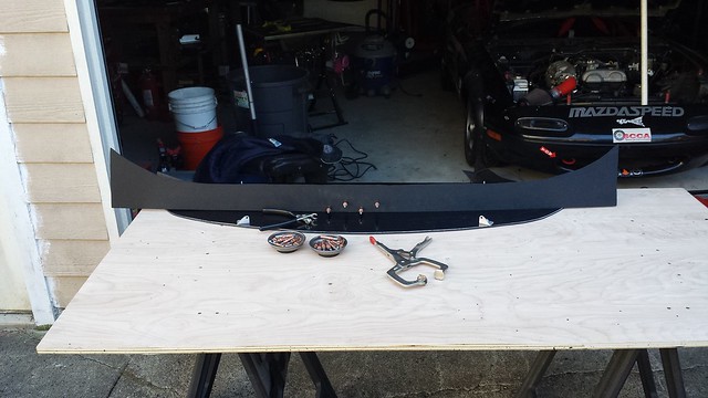
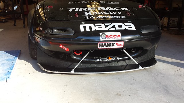
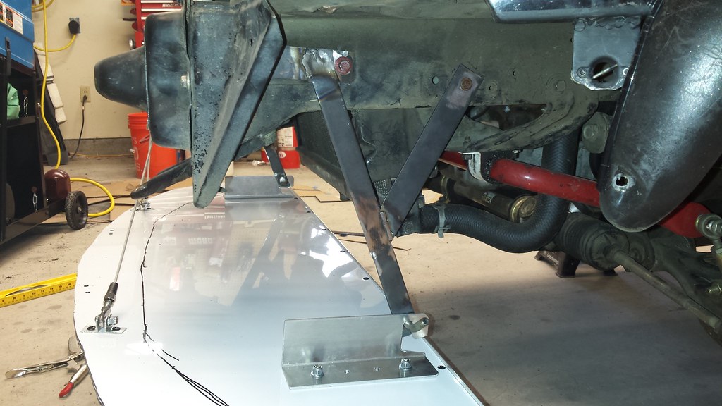
And then finally completed assembly and riveting, and got it mounted in place:

20170128_134644


It was a ton of work but now that I have a good, solid design, replicating it will be relatively straight forward. Hopefully I don’t find any crazy weaknesses with this design that’ll require another complete rethink.

Aero: Front Splitter

The biggest concern with making a splitter for me was that it had to be fairly easy to take on and off for loading and unloading, so the entire build is made with that in mind. I think I’ve accomplished that, as by releasing 2 pins and 2 dzus fasteners, the splitter can be lifted free from its mounts.

The constraints that the splitter must live in for a D Prepared car are:
It may not be further rearward than the leading edge of the front wheel opening.
It must fit below the silhouette of the car as viewed from above.

Given that, the first thing to do was measure measure measure and make a template:

20160220_172553

20160225_201451

20160225_202538

Next I wanted to make a set of mounts that would do most of the work of locating the entire assembly both laterally and longitudinally. I had a fairly large length of 1/8″ Aluminum Angle, and went to town with the drill and sanding drums. The hook portion will take care of the longitudinal location, and the mounts will be placed flat against the chassis mounts to locate them laterally.

20160310_220614

With all the ‘easy’ stuff done, I wanted to make the base of the splitter so that we could start working off of something more consistent that cardboard. The material I chose was 1/8″ Dibond, which is 2 thin sheets of Aluminum with a solid plastic core. A single sheet wouldn’t be strong enough, so I used some of the stronger 3M Double Sided tape to bond 2 sheets of Dibond together.

20160312_111138

I spread out some steel and lead to evenly press the 2 sheets together.

20160312_111740

After more measuring and fitting, I finally had a starting point:

20160312_120211

Now that I had it at a reasonable height, I could start measuring out to build the chassis mounts. Once those were fixed in place, I drilled out 3/8″ holes in the mounts and welded the ‘hooks’ I made to the backs of them, so that the weld metal wouldn’t interfere with the splitter mounts.

20160314_165456

20160314_132749

With the rear of the splitter fixed in place, I could start making a mount for the fronts. I built it to bolt to existing holes in the bumper support. Harbor Freight actually had excellent ends for the 3mm cable I used. I used a pair of Forked Cable Ends for the chassis side, drilled out to use 1/4″ quick release pins, and used a pair of Eye Terminals for the splitter side.

20160314_165418

20160314_175800

Finally having the splitter hung and being supported 100% by the car was a big moment for me, as the end was in sight and it finally started looking useful. I noticed however that in order to actually get my hands under the bumper and crash structure, the crash bar needed to be notched:

20160324_182600

With all of the mounts sorted, it still felt like it had a bit more flex than I was comfortable with. I used a length of 1/2″ aluminum angle along the rear edge of the spoiler to add strength. Fortunately, I had Superman there to help with the riveting work.

20160313_164757

For the air dam, I used 1/8″ ABS as it’s sturdy and easy to work. To join the ABS to the Dibond, I picked up some garden / paver edging from Home Depot Racing Supply. It’s nice and sturdy plastic, but also very light.

20160325_091228

Everything got disassembled for a couple coats of paint to keep the rust at bay:

20160324_181254

20160325_090212

And finally, put back together to be viewed in all its majesty 😀

20160325_184318

20160325_212604

I think maybe she might need a wash. Before then, there’s lots more work to do in the month or so before the next event.

Aero Prep Work

One of the things that drew me to the Prepared category was the possibility of some limited, but useful aerodynamic mods. Specifically, the  rules allow a 10″ spoiler in the rear, and a front spoiler / splitter that fits 1) completely under the body work, and 2) does not extend rearward past the leading edge of the wheel arches.

The time has finally come.

First thing’s first: lots and lots of cussin’ fiddly work with cardboard to get everything measured properly. Specifically, getting the outline of the nose of the car for the splitter, and the contour at the rear of the car for the spoiler.

20160220_172553

20160223_150903

20160223_152022


With that out of the way, I realized that I was going to be having the bumper on and off the car a bunch more, both in the fabrication process, and then in the future when to work on the splitter & mounts. Time to make it as quick release as possible. Most of that work has been done in prior jobs (cutting the fenders necessitated adding a dzus fastener per side to hold the bumper to the fender, and I got sick of dealing with hard to reach 10mm nuts, so I did another pair in the corners), but there was still the core support bar, and a nut & bolt per side where the front flares meet the bumper. I used a couple more of the pre-made spring brackets, and mounted the screws on the bumper to mock everything up:

20160225_135707


I decided to use a pair of short hacked-off sections from the original bumper mount to mount the Dzus receiver to, as they were convenient and could be removed if I was ever working on the engine bay with the bumper removed (pulling an engine, for example) so they wouldn’t be sticking up looking to draw blood.

20160225_172352

Beat it to fit, paint it to match…

20160225_200310


And then added a riv-nut per side so that I wouldn’t need to fiddle with a nut to remove that corner of the bumper

20160225_202211

With that, it was time to start positioning the front spoiler so I can work out where it’ll mount to the chassis:

20160225_201451


Turns out there’s a very convenient spot. The 2 holes on the frame rail on the far-right of frame were originally for…something some engineer found useful, I imagine… and are pre-threaded. I’ll be able to make a pair of brackets that drop down from the frame rail to meet the rear spoiler mounts.

20160225_202538

These are not the final design, but they should make a solid starting point for the rear mounts. I’ll probably be able to cut 1 in half and use it for both.

20160223_152340


And finally, we ripped some ABS apart with a jig-saw and scribed out the lower and upper ‘maximums’ for the spoiler. I’ll need to notch it in 3 places where it will meet brackets made of 2 x 1/8″ aluminum as well, but more on that in the future.

20160225_230342