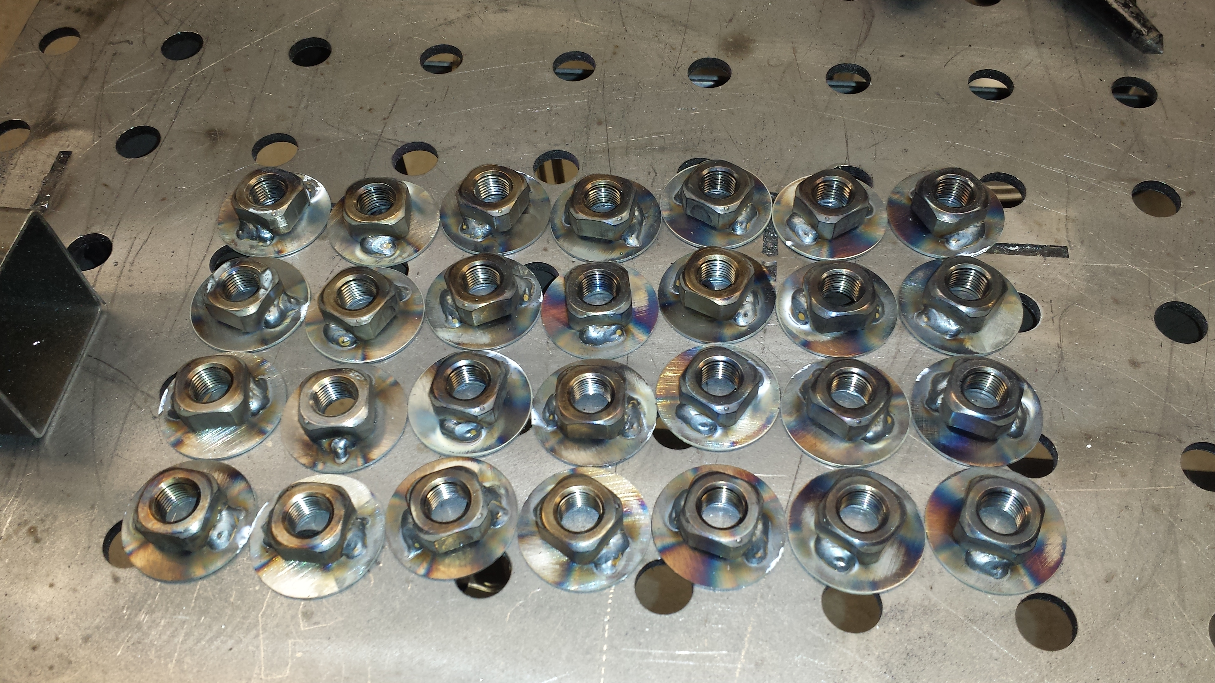
I finally got sick of dealing with the shortcomings of the VP racing jugs and their tiny air vents, leading to it taking forever to drop a few gallons of fuel into the car. While I don’t need to do F1 pit stops or anything, some of the TT style events I’ve been running have fairly quick turn-around time between sessions (*especially* with a co-driver), and so cutting a few minutes off of that will be helpful.
So I upgraded to a pair of Hunsaker Quick-fill dump cans:
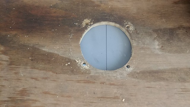
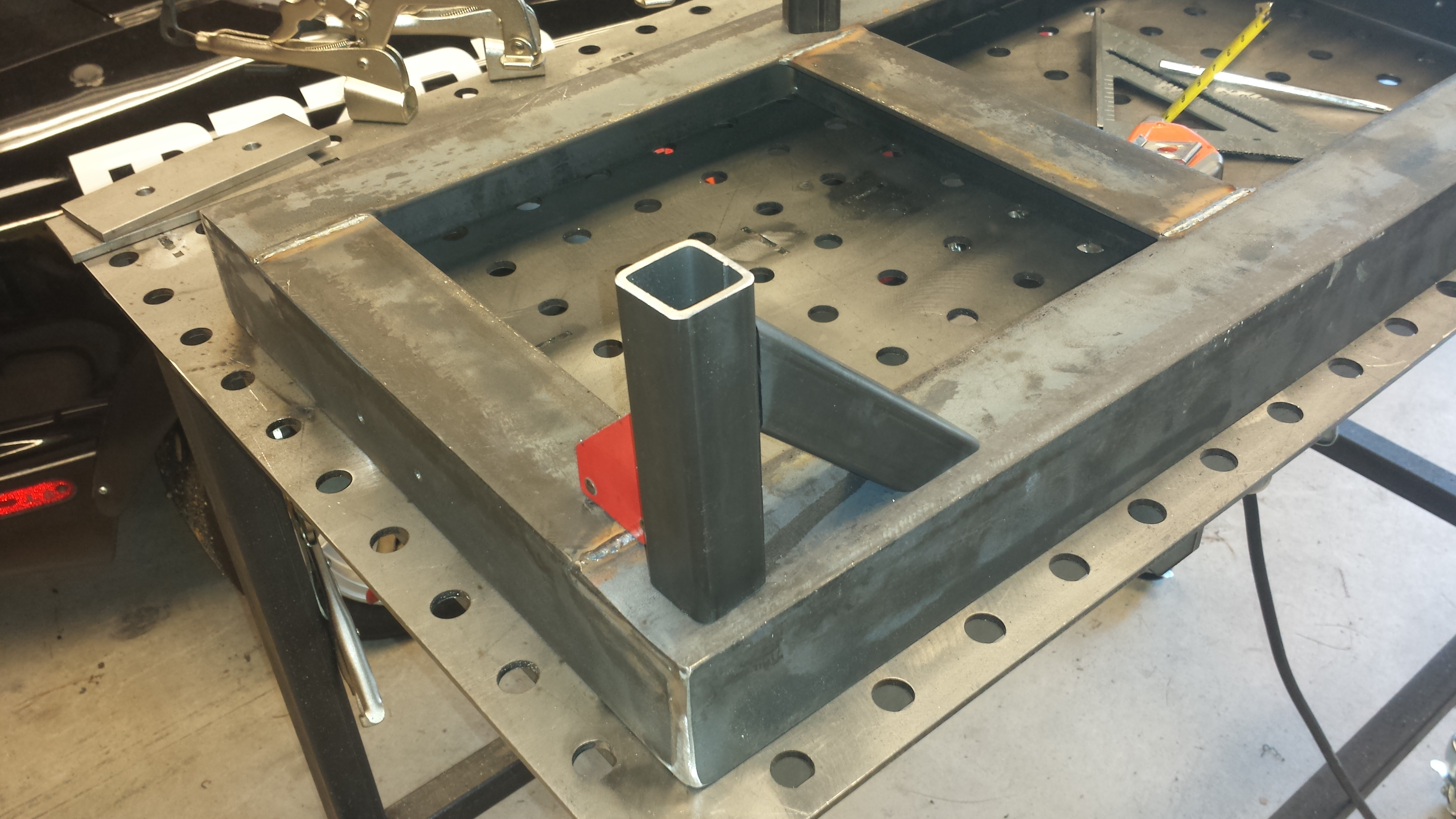
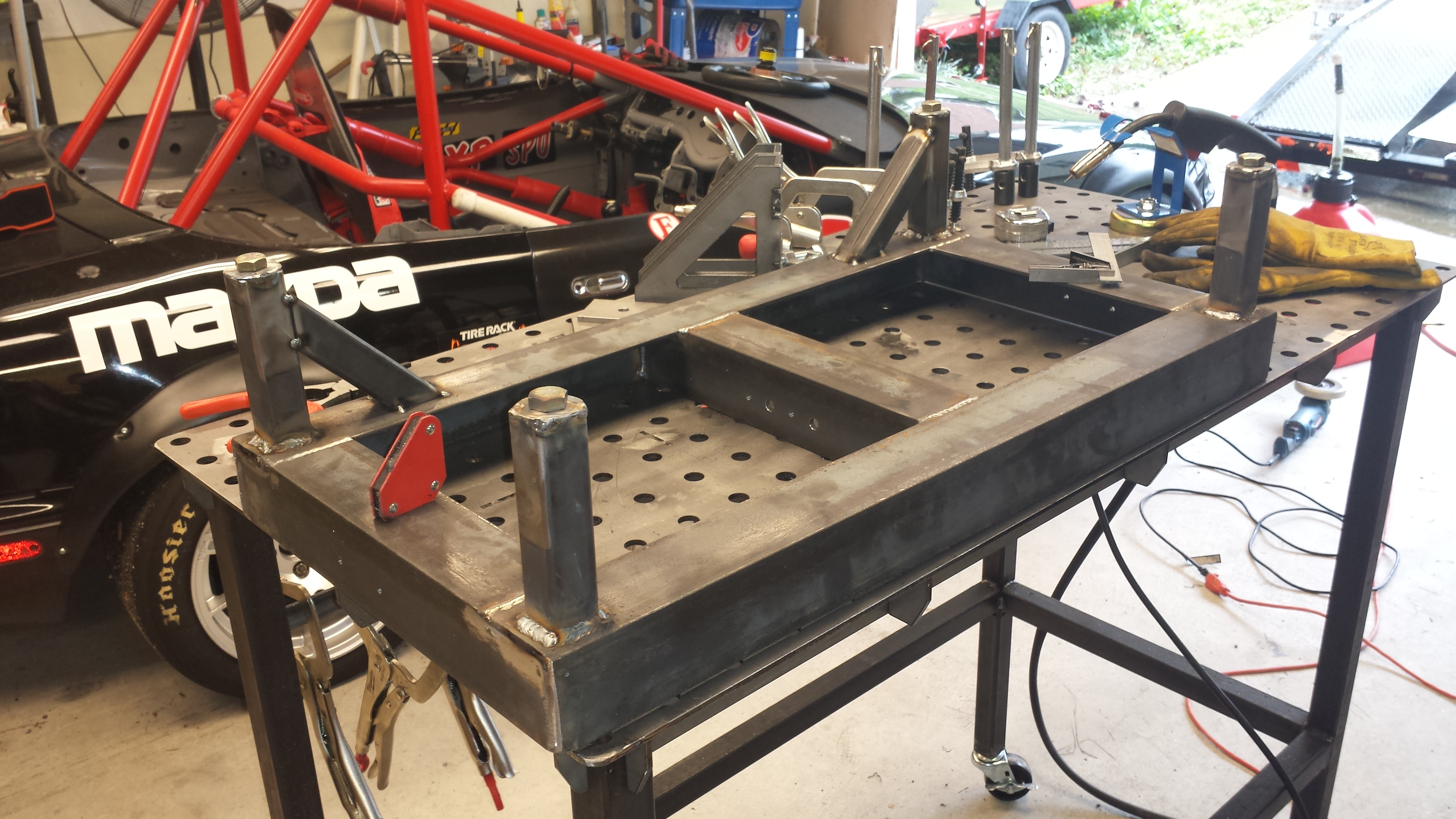
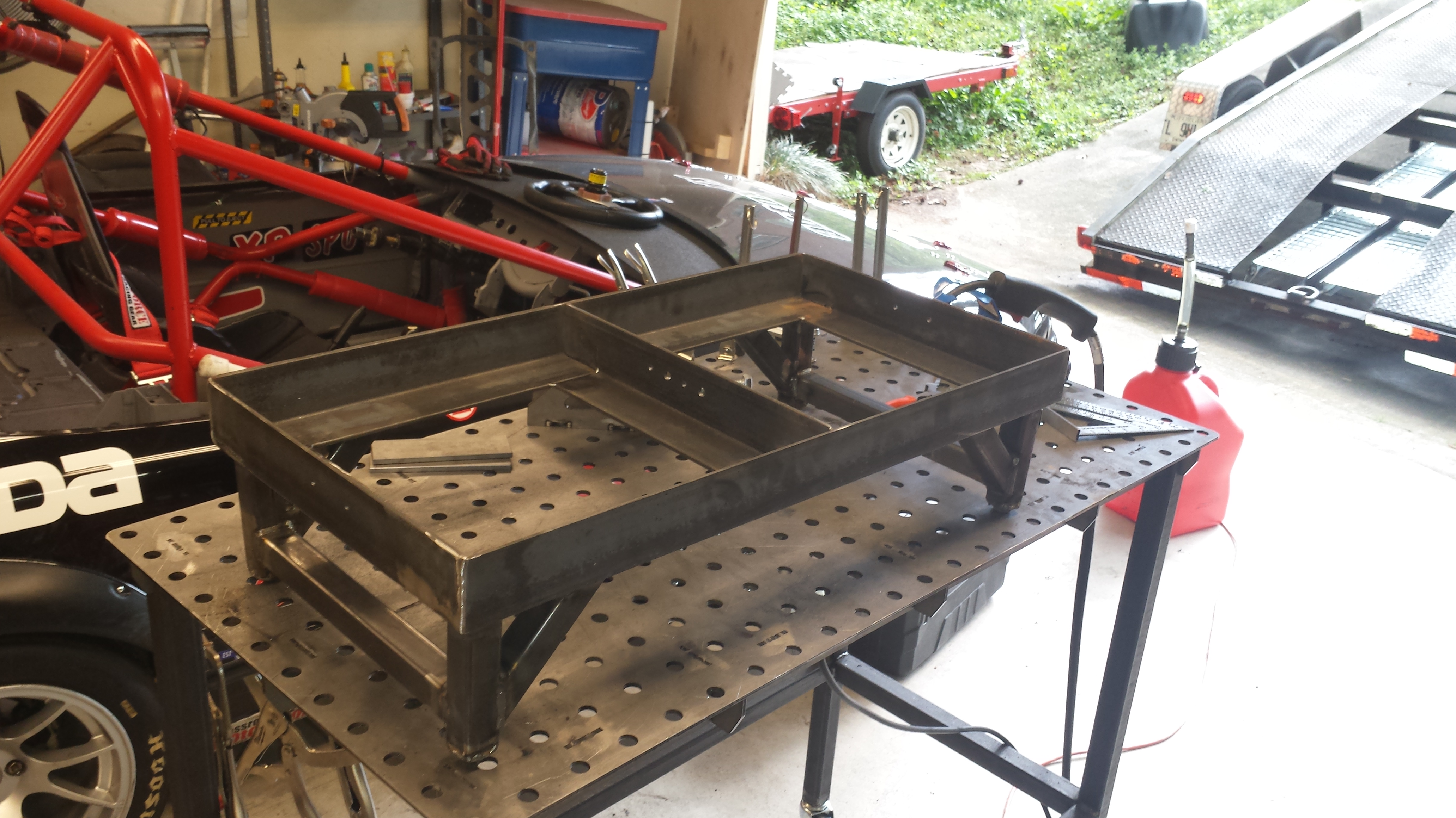
The Hunsaker jugs are a bit squatter than the VPs and so they won’t fit in the old VP fuel jug rack (something like 12-1/4″ vs 10″-ish for the VP) so a new solution needed to be made.
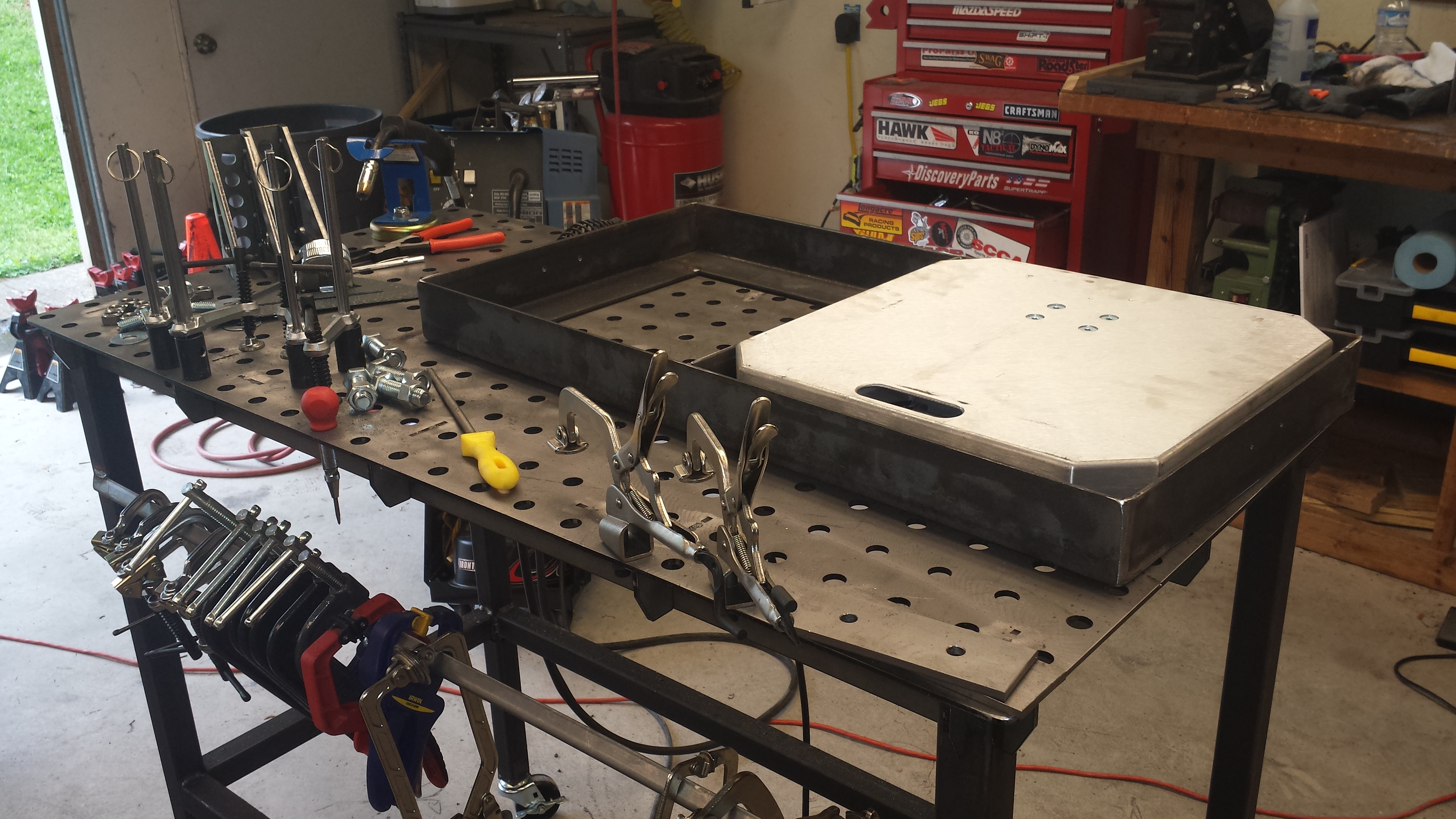
Time to break out the saws and scrap steel.
And the welder…
Add a couple coats of paint and call it good.
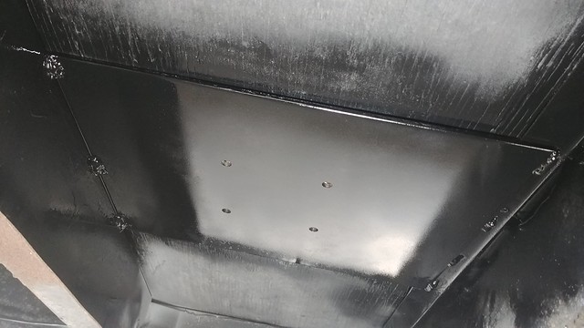
I’ve gotta say, having some light in the trailer makes a MASSIVE difference. It’s a damn sight better than working in there after hours with a drop light.
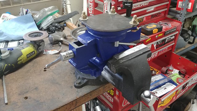
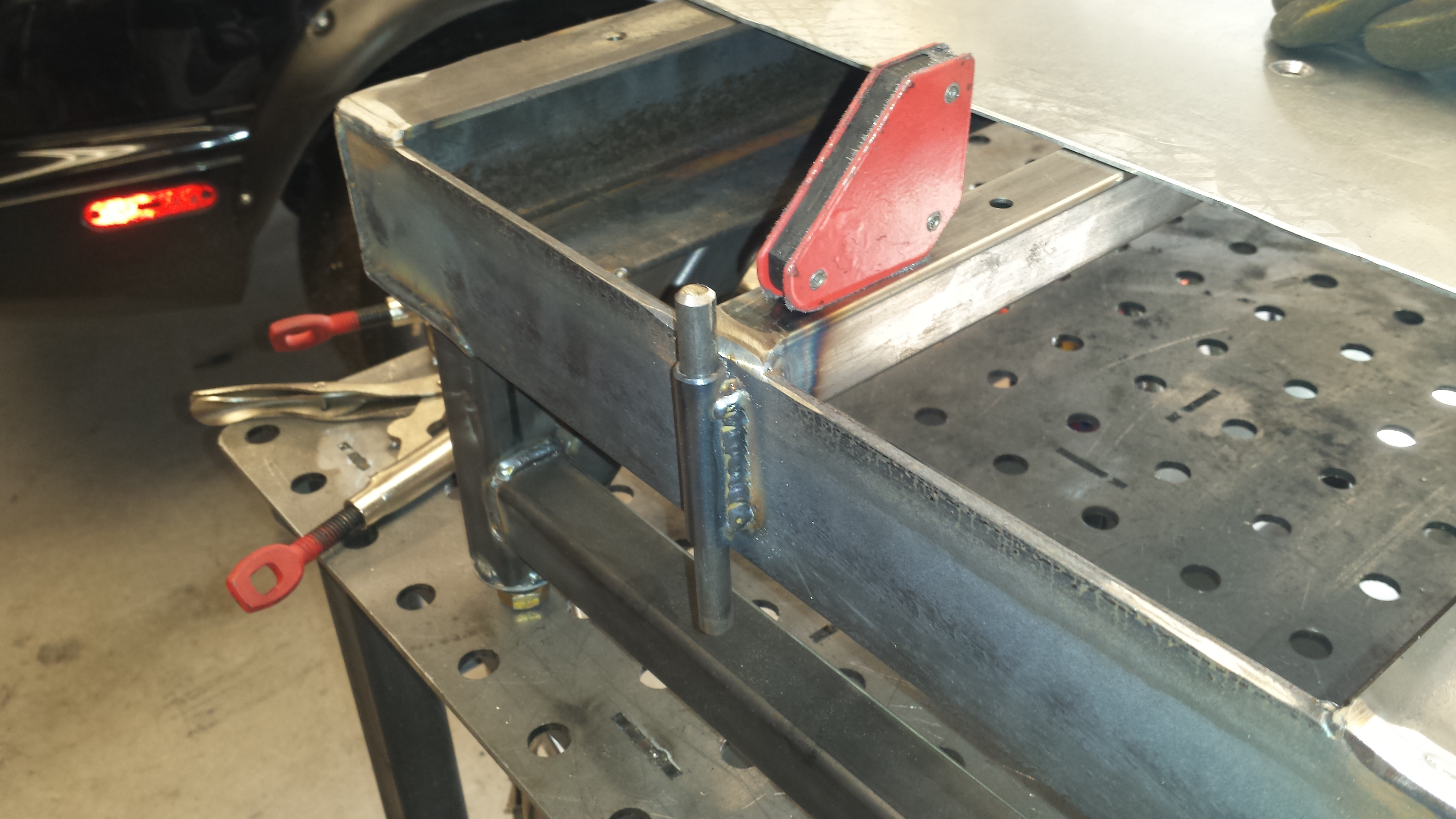
I got a dumb idea for a useful thing that I just couldn’t shake until I built the thing, so I built the damn thing. It occurred to me that having a vise in the trailer for “break it ’til it’s fixed” type work could be a useful thing to have. But I don’t have a really good place to store it, much less somewhere I’d be able to really hammer on stuff without breaking whatever it was bolted to.
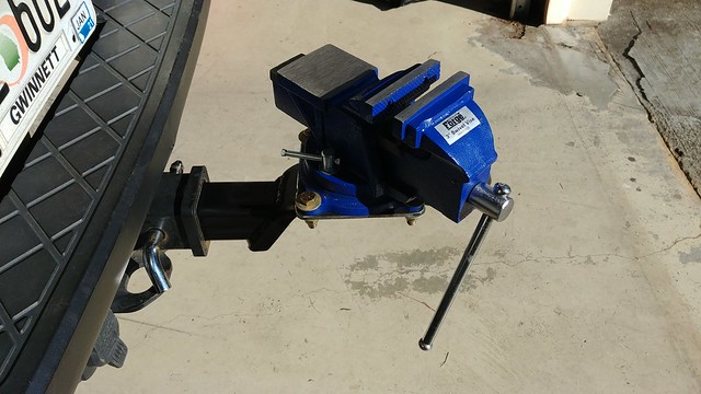
I realized that my truck weighs 6,000 lbs, tows almost 7,000 lbs regularly, and has a 2″ square hole at the back that takes readily available, cheap, off-the-shelf hitches.
The prototype stage involved a trip to Harbor Freight. One small bench vise, one 2″ trailer hitch, and one small ATV receiver hitch to wall mount for storage.
I had to cut the top (depending on which way you flip it…) corner off the ball-mount portion so it didn’t interfere with the wall when in storage:
A bit of plate, a band saw, a drill press and a disk sander gets you a nice little mount for the vise:
A little welding:
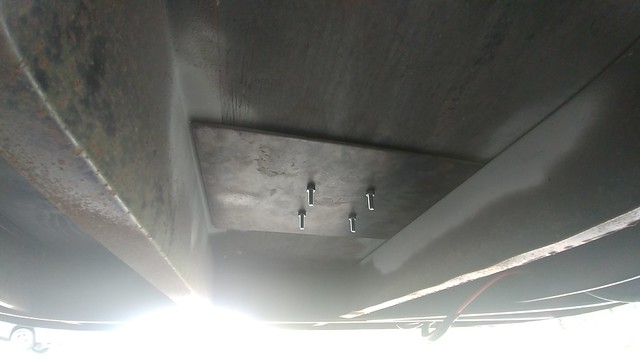
I welded a plate to the back of the ATV receiver so I’d have somewhere to drill into a wall-stud in the trailer:
It occurred to me that the D-ring on the wall mount would be a handy spot to hang a sledge hammer from. Because you always need a sledge hammer.
And finally, here it is in its ‘deployed’ configuratoin:
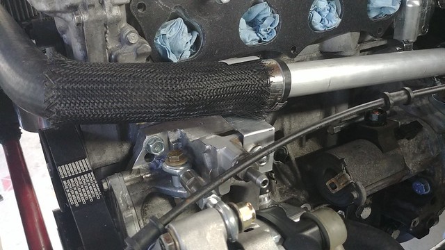
Thankfully for the most part, the cooling situation on these if fairly straight forward and a known quantity, though there’s *always* some custom work to be done.
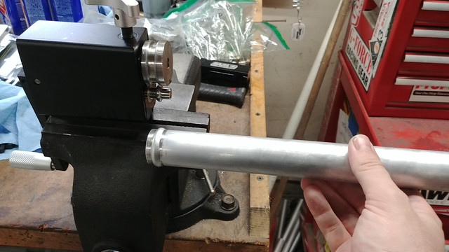
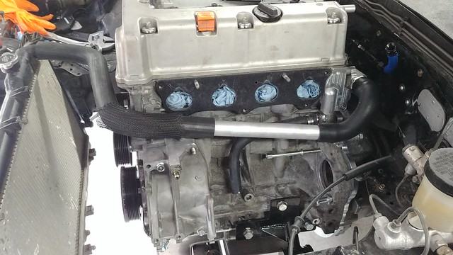
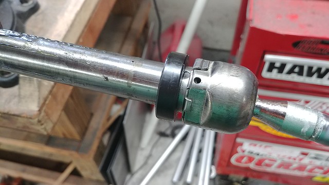
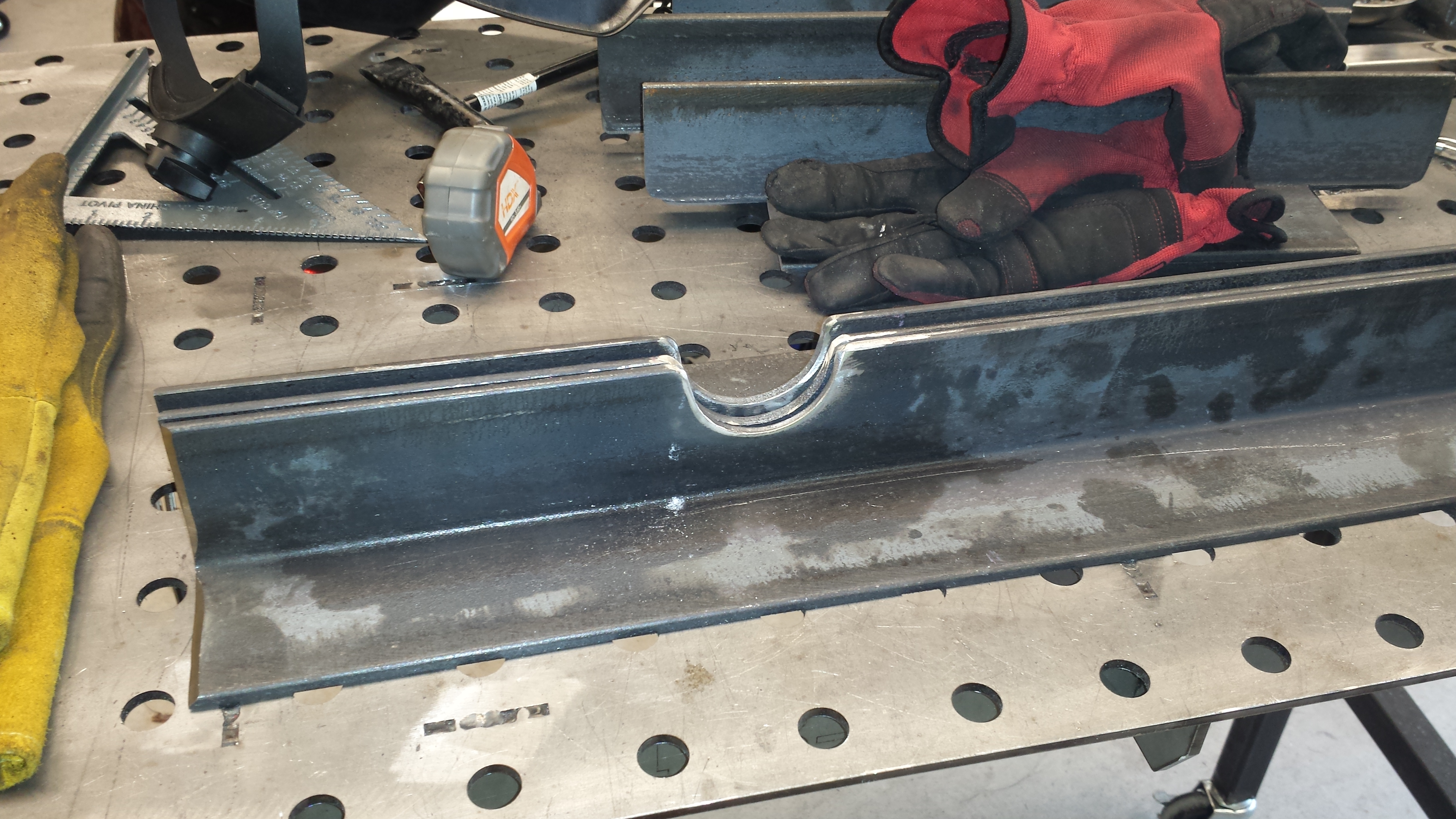
First thing’s first, the hoses. The upper hose can be made from a Dayco 72277 and a Dayco 72098, with a 12″ coupler between them, and the lower is a Dayco 71718. They’ll all be need to be lightly trimmed to fit, but they’ll get you most of the way there.
Of course, a 12″ coupler doesn’t seem to exist off the shelf, so I bought some aluminum tubing and a bead roller and got to work:
I made a strap out of a piece of tubing to secure the front of the upper radiator hose away from the front corner of the block, and the accessory belt idler pulley:
I’d been using a stock radiator for mock up so as to not risk dinging up the nice aluminum rad, but quickly found a clearance problem with the stock fan bolted on the thicker core aluminum rad, as it did not fit between the radiator and front sway bar.
With a slim-line fan ordered, I could get busy building mounts. I used the “through the core zip-tie” style ‘mounts’ it came with to secure it in place and give me something to aim at:
I cut the mounts out of steel plate. Aluminum *might* be strong enough for this (especially some CNC’d billet mounts), but this is critical enough that I’ll take the weight penalty for over-building it. I did turn up a set of spacers on the lathe out of aluminum, and the fan is bolting through weld nuts on the bottom of the mount plates
With the critical features of the lower mount done, the simpler top mount could be made:
A quick test fit shows PLENTY of room to the front sway bar:
Once all the critical fitup was done, less critical Speed Holes can be drilled:
A lick of paint and some foam-rubber insulation to seal the fan to the core, and prevent chafing:
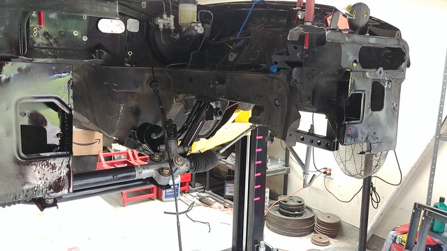
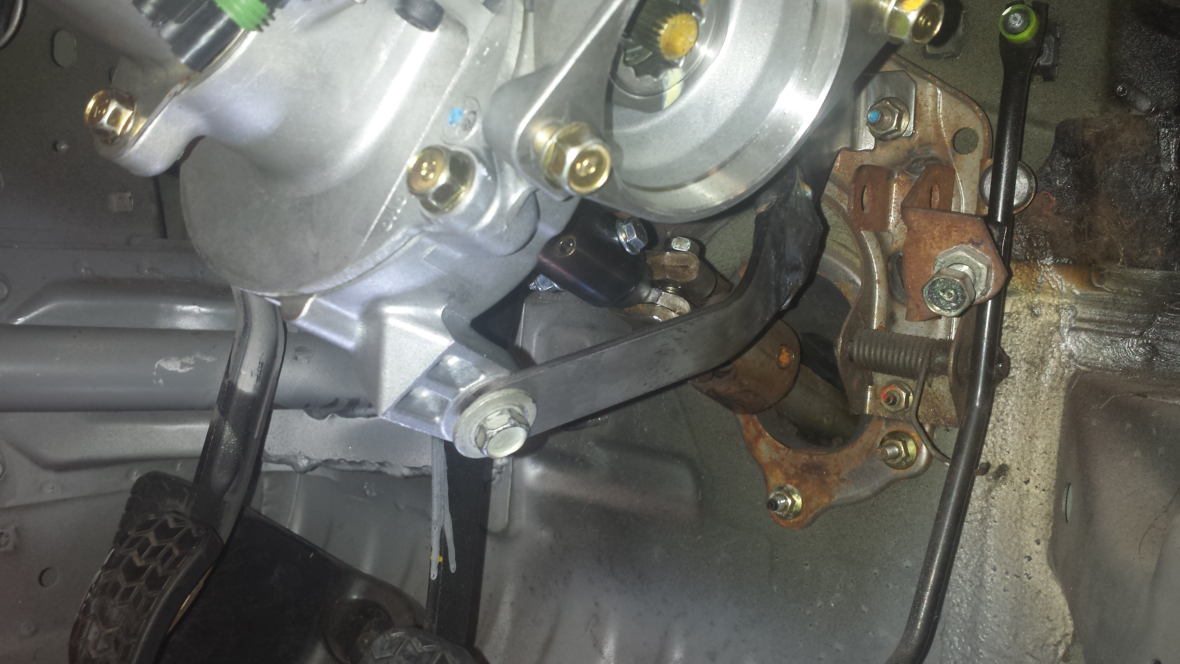
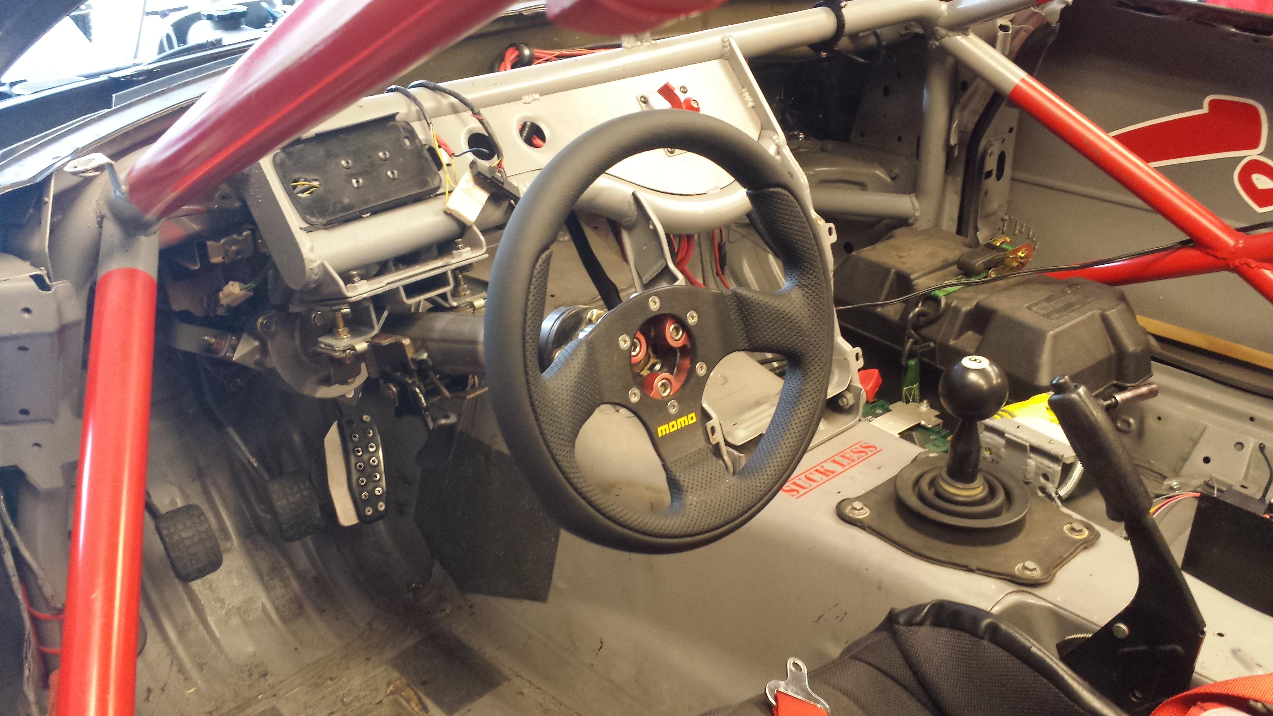
It’s time. It’s finally here. With the Chasing the Dragon Hill Climb complete (and successful beyond my wildest dreams, making the fastest pass by a Miata ever), it’s time to put the bigger, lighter Honda motor in the race car.
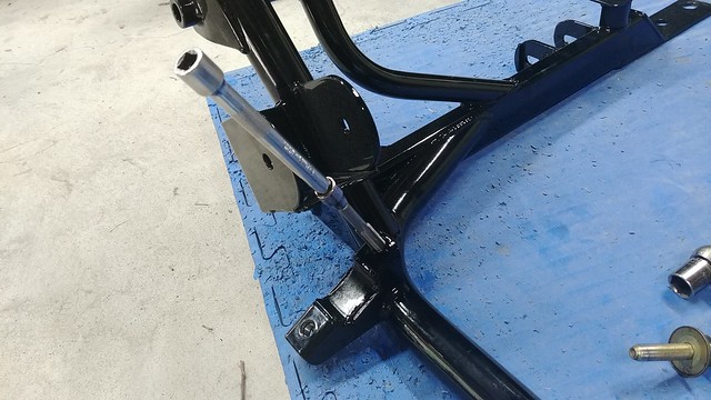
Unfortunately however, things got off to a rocky start. Prior to the Hill Climb I started test fitting things to the V8Roadsters subframe and all was not well.
The first bit of prep was to get the steering rack on the subframe. So as to not lose the NB rack bolts I figured I’d put the bolts into the threaded holes in the subframe for safe keeping. 3 out of 4 had powder coat completely boogering the bolt holes. Adding to the fun, the thread pitch of those holes is M12x1.25mm, which is the one M12 tap I don’t actually have in stock. A quick Amazon shopping trip and a couple days later, the tap comes in. After chasing the threads in the good bolt hole and 2 of the 3 bad ones, I realize 1 of the engine mount brackets completely blocks access to the 4th. Improvise and overcome right?
Turns out, a 5/16″ 12-point socket makes a good-enough narrow access tap wrench for an M12 tap.
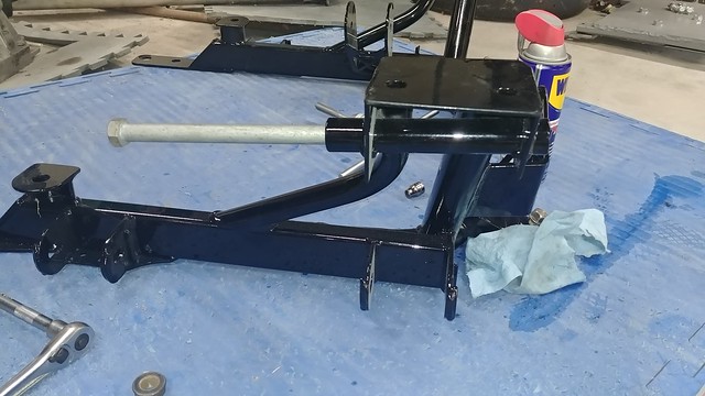
That’s not great, but a pretty small issue all things considered. Then a friend (thanks Nick!) who has experience with V8R subframes suggested I check the rest of the holes, and that’s when the big problems started. I could not get the upper control arm bolts through the bores at all.
I went as far as creating a custom tool with some rod and sand paper to grind the powdercoat out of the bores, thinking it was a similar issue to the steering rack bolts, but no, the bore was shaped like a banana. I still don’t know if it was overheated when it was welded to the frame or what, but it wasn’t great. And given that it left the shop like that, their QC wasn’t exactly giving me warm-fuzzies either.
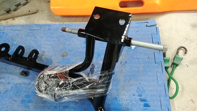
To KMiata’s credit, they handled getting a new one shipped out and return shipping for the bad one to V8Roadsters to ‘investigate’. Once we determined just how bad the problem was, I had a new one in hand a few days later.
And check it out: bolts that go in without any hammering or clearance! What a concept!
Next it was time to get the steering rack prepared. Because of tight clearance to the oil pan (…a recurring theme…), all the hydraulic fittings on the steering rack housing had to be cut off. I used a 3/16″ rivet and some JBweld to seal the holes.
Next I discovered that Mazda changed the design of their inner tie rod lock washers. The old style washers sat on the OD of the tie rod’s threads, so it was flat between the rack and the tie rod. The newer style lock washers have a shoulder that goes on the over OD of the rack. That prevents my steering rack limiters from seating all the way at the ends of the rack, taking another 3/8″ or so of travel out of the rack.
I corrected that by throwing the limiters in the lathe to put a counter-bore in the ID to clear the washer on 1 side, but still ride nice and snug on the rack:
Time to start disassembling the car:
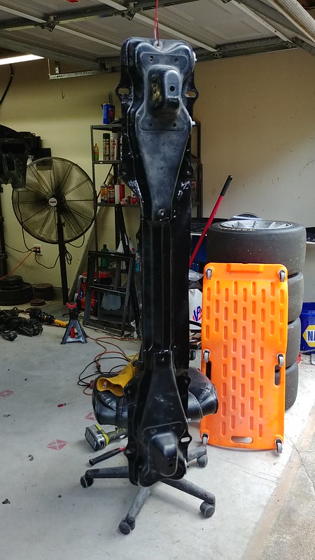
Given that I’m going to have to install and pull the drivetrain several times over the course of the coming build, I also wanted to remove the upper radiator support (which doesn’t actually support the radiator in an NA Miata), and make the front bumper bar into a bolt-on piece. As you can see, the engine and transmission will come out of the car practically straight:
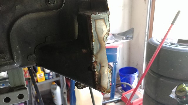
A little bit of cutting and welding later, and the front bar bolts to the chassis legs:
It’s so much easier pulling the whole thing as a unit:
With the rack put back together, I could finally put the subframe in the car. Unfortunately there’s evidence that my car has been in a minor front-ender, which appears to have slightly tweaked the subframe pickup points. Because of that, I had to pat my head and rub my tummy and figure out which order the bolts wanted to go in so that all the holes actually lined up, but once I figured out which hole was the furthest out and started there, it all bolted in.
I found a couple of bad ball joints during disassembly, so I called Mazda Motorsports and re-loaded the parts cannon to get good parts on board, but once that was done, everything bolted up nice and easy (including the steering rack)
The first outing with the trailer went well, but I really wasn’t happy with the new D Rings. Or at least, with how they were secured to the trailer.
They have fairly large backing plates, but at the end of the day, they’re still just secured to plywood.
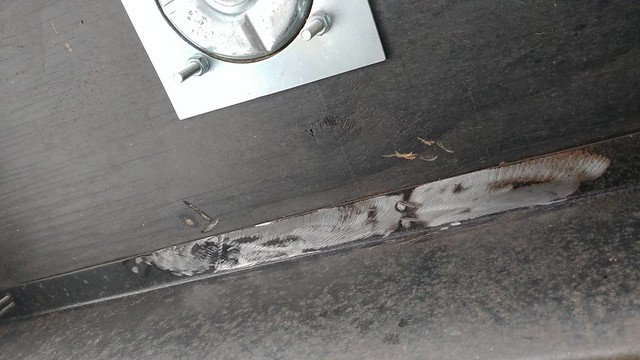
Cinching the car with ratchet strap induced a visible bow in the floor, and didn’t exactly give me that warm-fuzzy feeling about its ability to hold the car in place. More drastic measures needed to be taken in the form of a pair of 12″ x 15″, 3/16″ thick steel plates to be welded to the frame of the trailer.
The first job was to cut off a handful of floor screws that were hanging right in the way, because of course they were (see photo above).
I had to grind a bunch of paint and surface rust off so I have something decent to weld to:
Because I wouldn’t be able to get at much of that steel after welding, I hit the trailer frame and the tops of the backing plates with a coat of weld-thru primer:
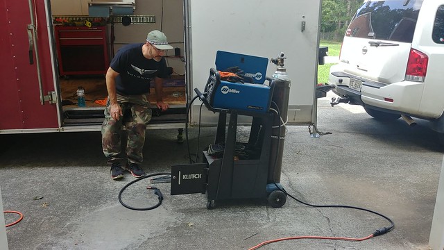
The next day, both the trailer and the welder got dragged up the hill. I’ve never had the occasion to use the 110v plug adapter for the welder, but it did just fine. I’m honestly surprised I didn’t blow the garage circuit breaker.
It was a multi-step process of figuring out where they needed to be (the frame is made of Z channel, so 1 side I had to be right against the frame rail, and the other I had a couple inches of flat steel to play with. A buddy helped me get them more or less centered from above, then we popped a pair of transfer punch marks on the plate. Drilled those, took it back up and bolted it to the floor to confirm alignment, then back to the shop to drill the other 2 holes. Rinse and repeat. But once that was done, the floor supported the plates for welding, which made that part significantly simpler.
The view from above, centering line definitely close enough.
Without a doubt these aren’t the prettiest welds I’ve ever made, but they’ll do the job.
The finished product looks exactly the same from top-side, but I feel a LOT better tying a car to these now.
And because nothing’s ever simple: I had put down the rear ‘RV leveling’ jacks to stabilize the trailer as I unhitched it from the tow pig prior to welding. When I retracted them after we got done, 1 of them went up fine, while the other one just unthreaded the jack-screw, which shouldn’t be possible in normal operation. I the jack off the trailer and disassembled it in the shop and found that a roll pin that secures the inner washer (to prevent it from just unthreading) had sheared off. A quick trip to Ace got that sorted out for about $0.35 (and a lot of cussing)
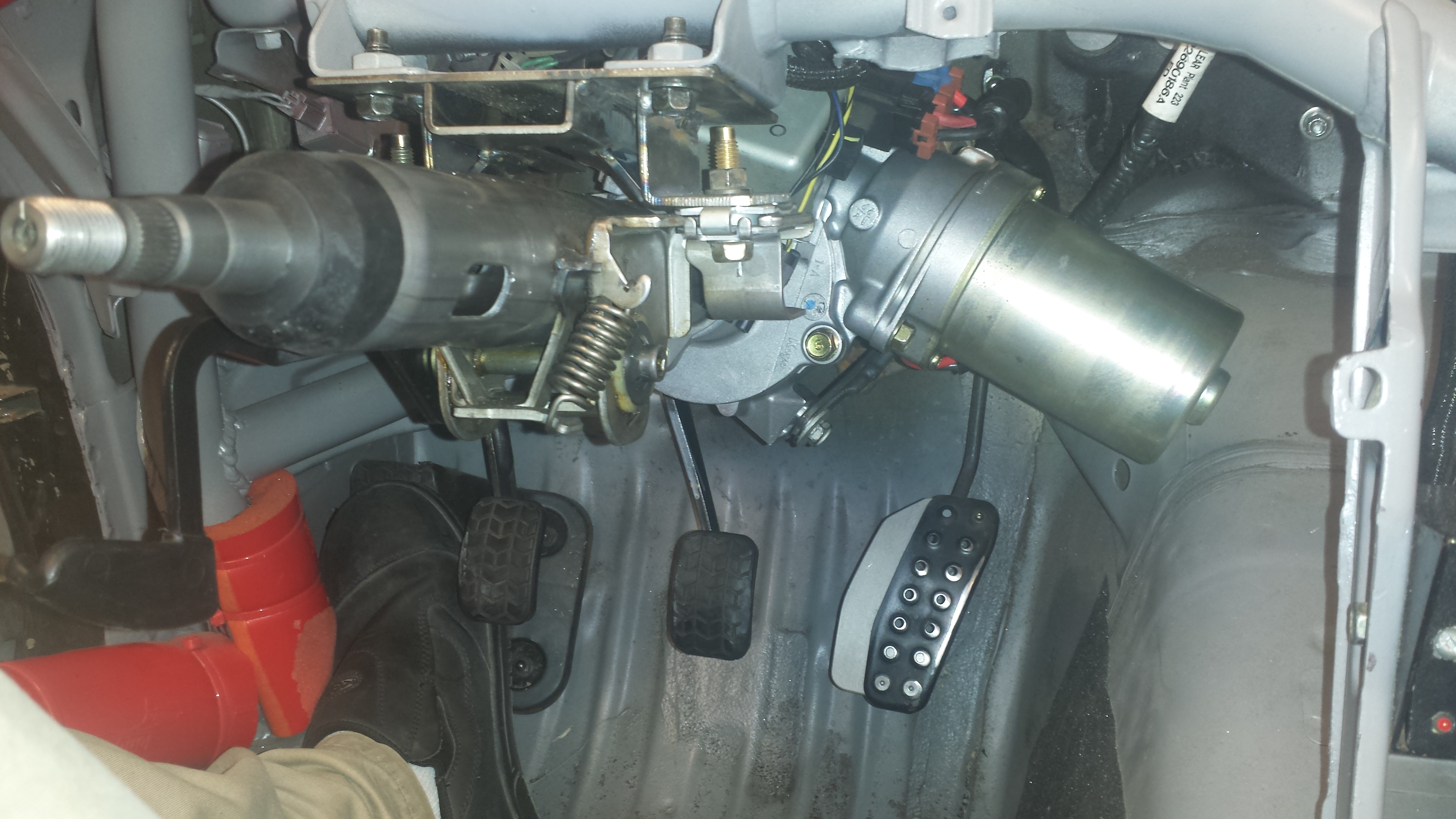
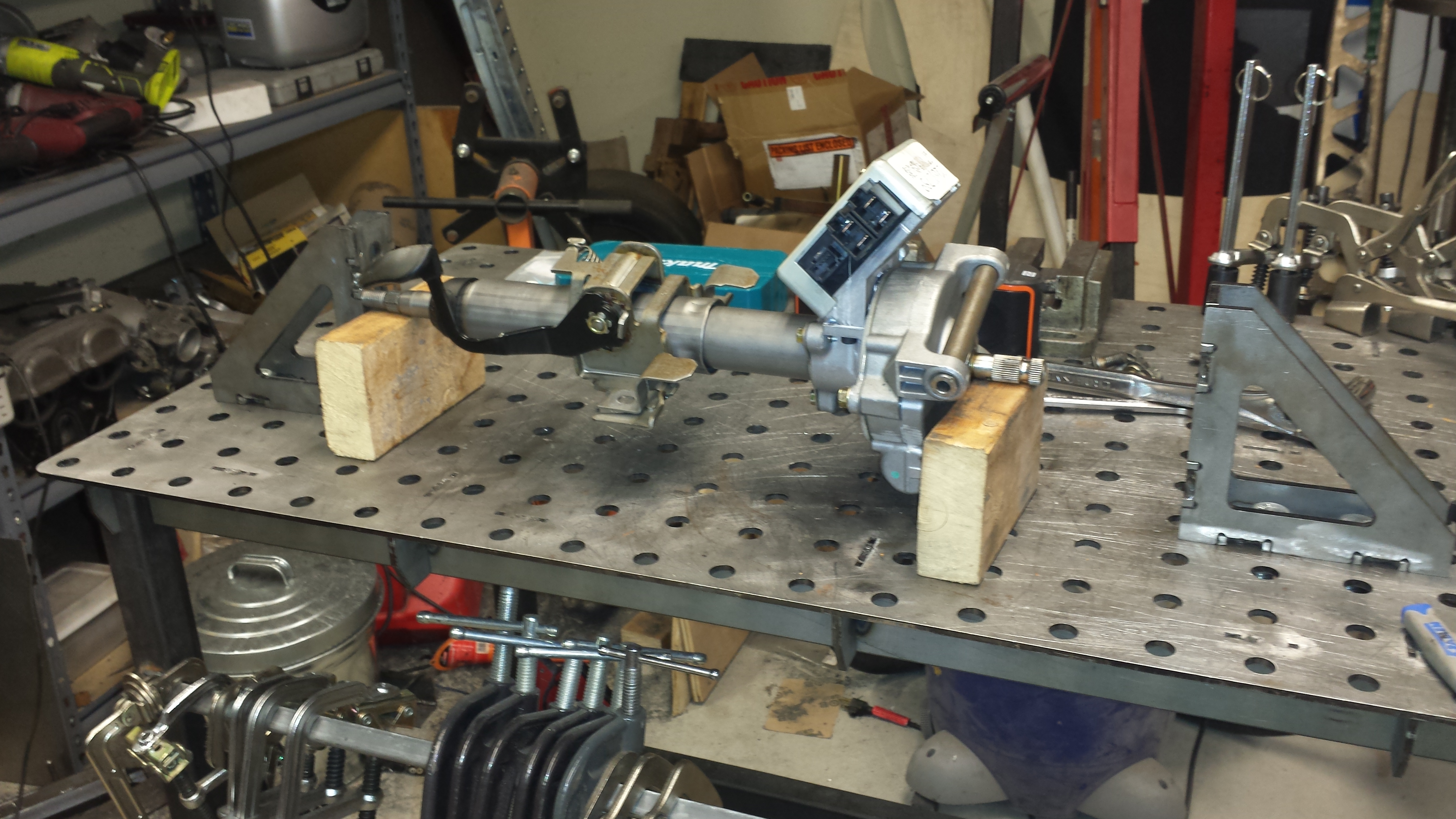
With the column completed, I could get it mounted in the car. Woohoo, it fits! And SOMEHOW, the steering wheel spline size is the same for both the GM and stock columns. My quick release bolted right on.
While tiedown straps are nice and simple, they’re not exactly sturdy enough for keeping a steering column in place, so it’s time to break out the cutting and welding tools.
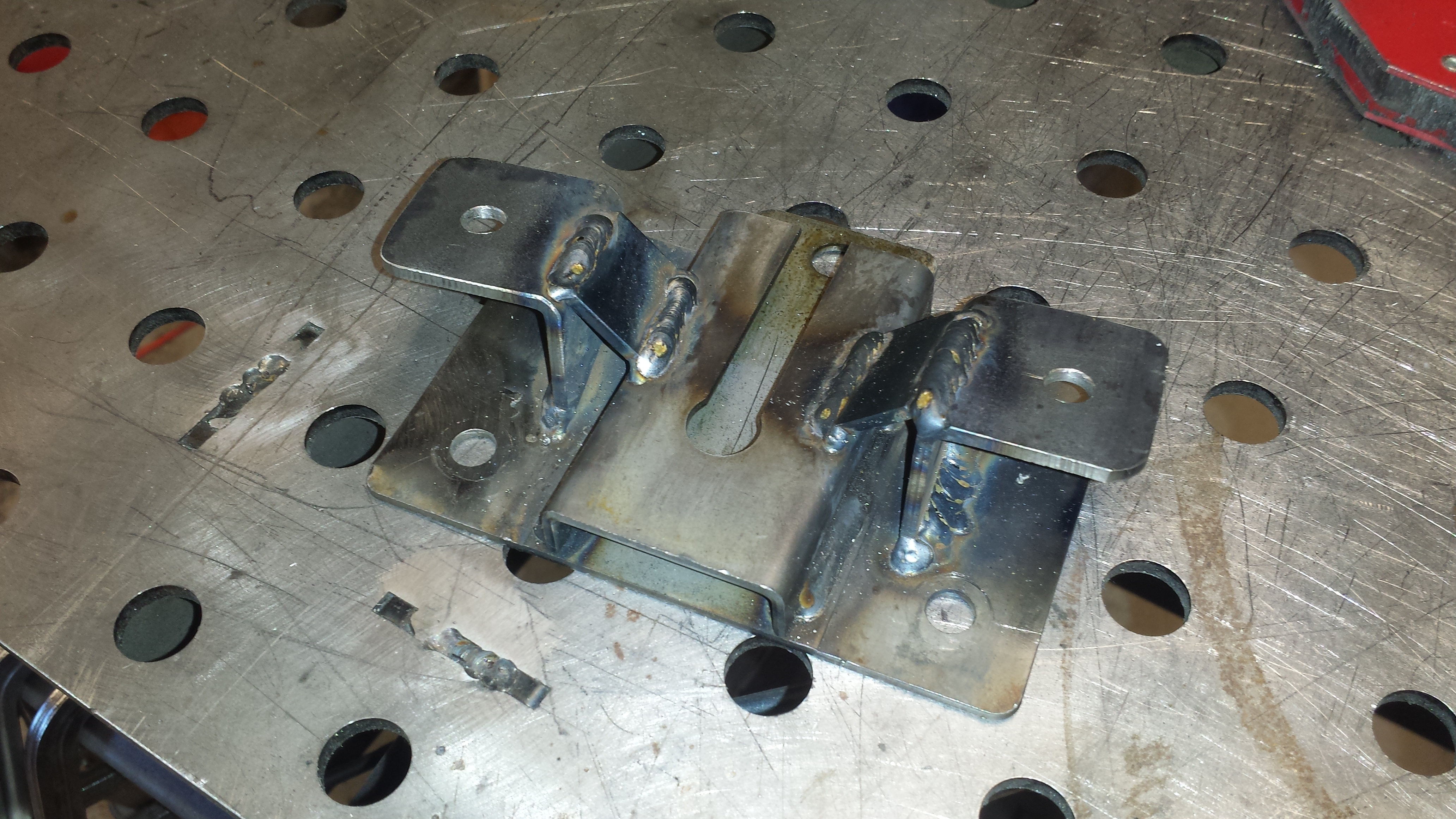
The Miata and GM column mounts are not parallel, so it took a little creativity to get everything lined up correctly. After a little bit of measuring, I realized I could cut the shapes I needed out of a drop of 2″ square tube. Everything looks parallel in the picture, but there’s about a 1/4″ slope on 1 side of each bracket to fix the difference in angle between the stock pickup and the GM mount.
The stock column mounting-plate made a good datum & base to fabricate from. The brackets are bolted to the GM break-away tabs as they would in the donor vehicle, retaining all of the safety features built in to the new column.
I added a couple gussets to stiffen things up, as there will be a fair deal of torque put on this mount during competition.
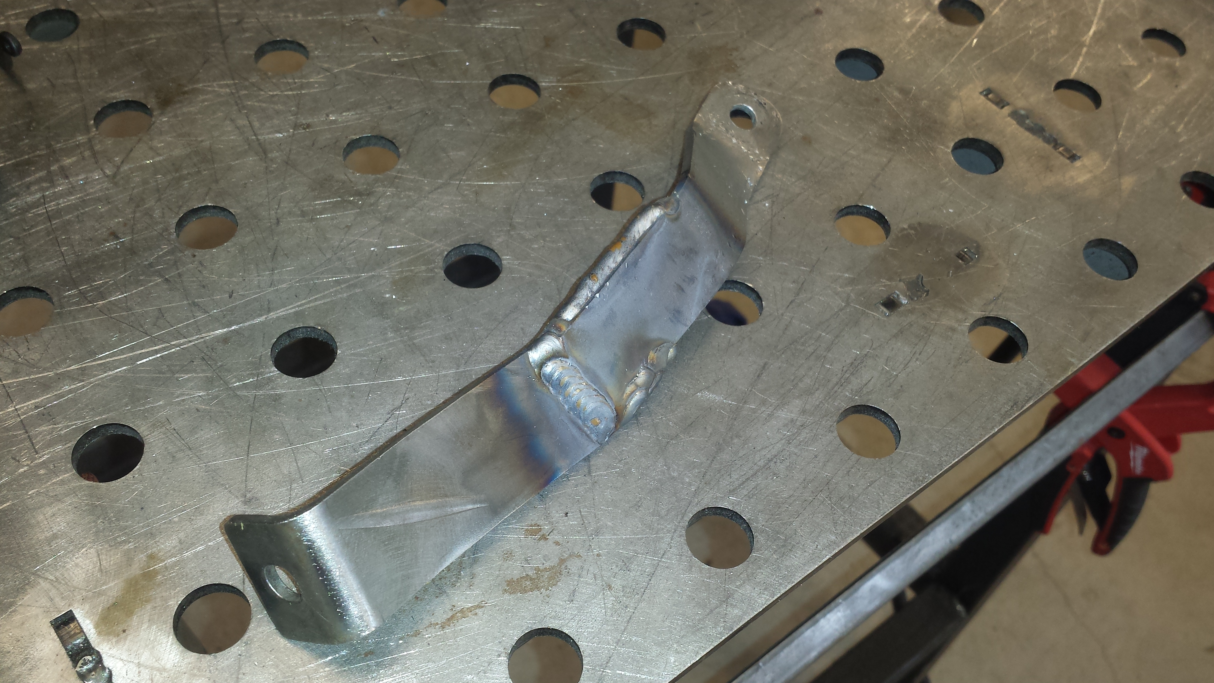
I hacked the lower mounts off of the sacrificial column, and used the stock firewall mount points as the basis for the new lower mounts. The left-side mount was by far the most difficult. It took quite a bit of jiggery-pokery to get all of the angles correct so that there was ample clearance for the brake pedal.
There was far more room to work with on the right-hand side.
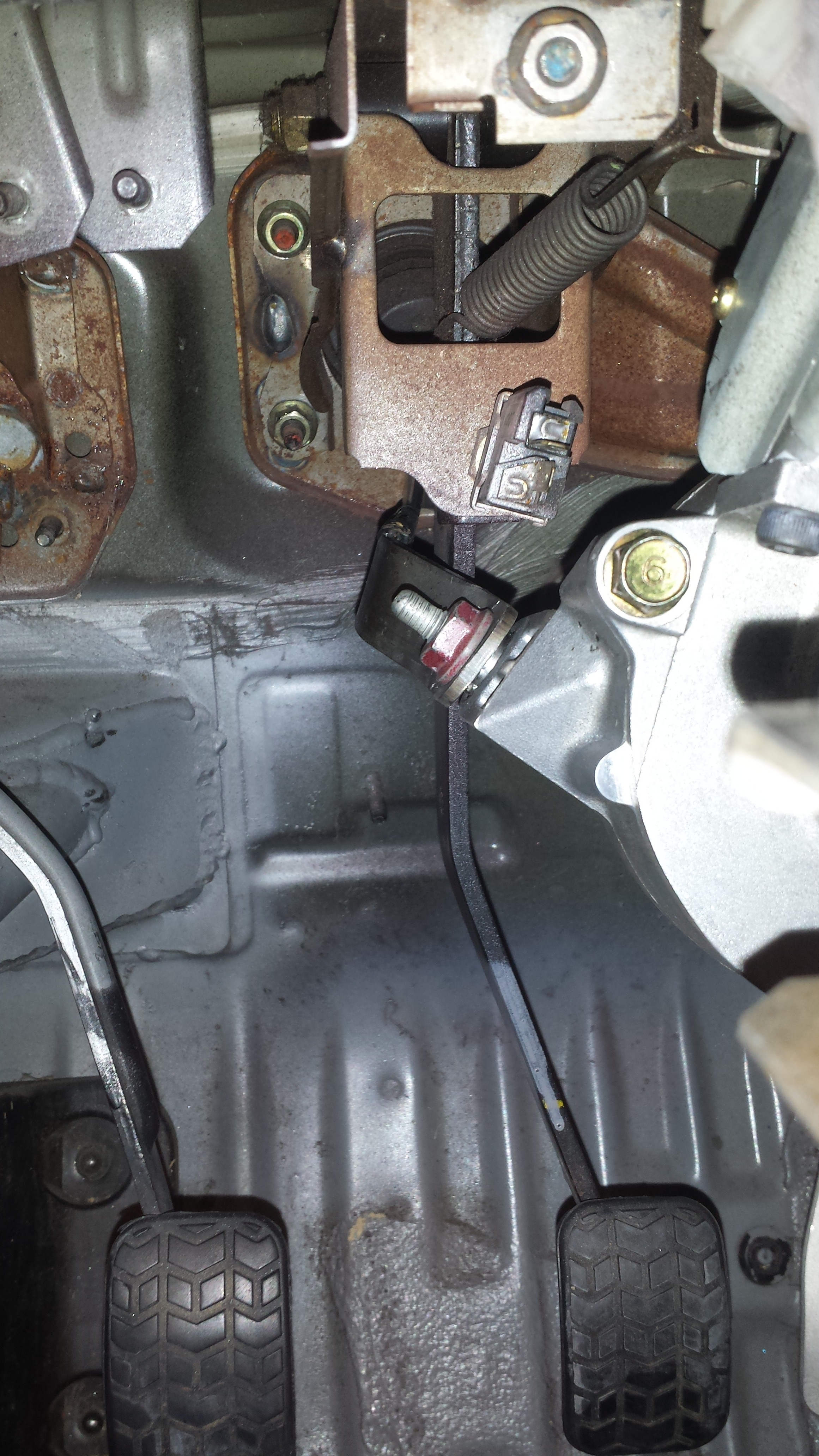
I’d been working with the motor disconnected, as it is big and heavy, and would make things far more difficult in this stage. The time has come to put it back on. Plenty of clearance in the footwell.
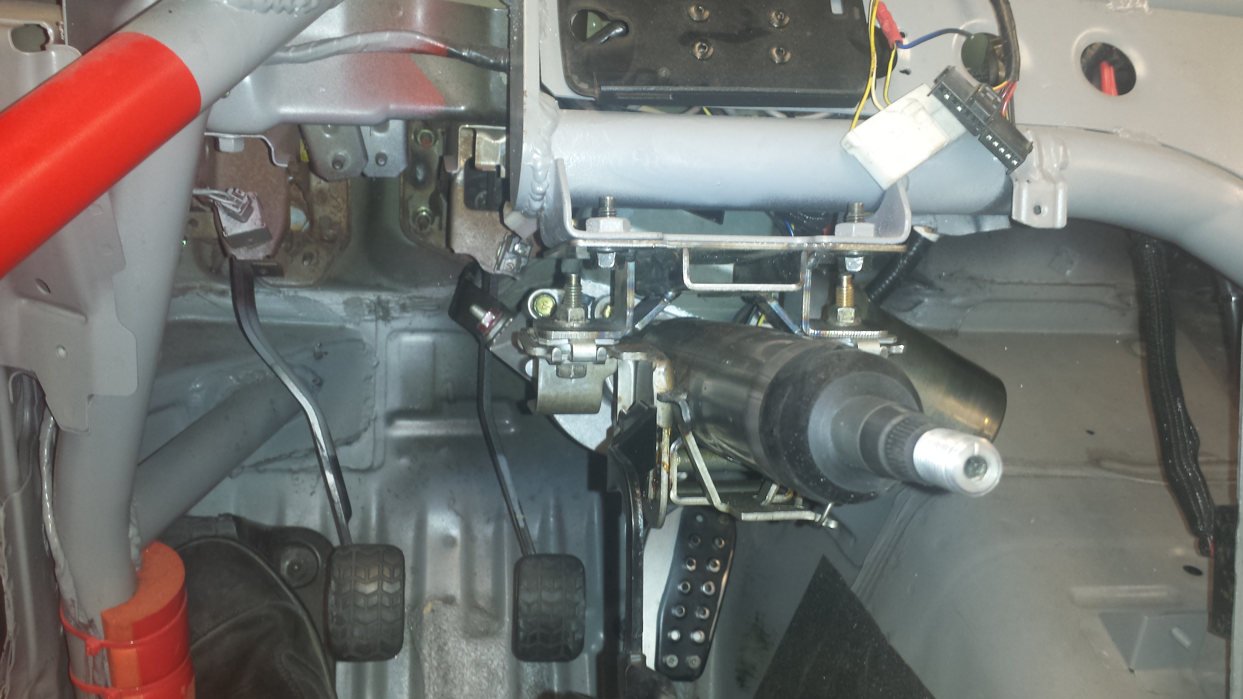
Also, check it! I can get about 1″ of tilt on the column (nearly the full stroke in the mounts)! I was fairly convinced that the tilt wouldn’t work with my install, but here we are. Finally, an NA Miata with the oft-advertised but never before actually seen tilting steering column!
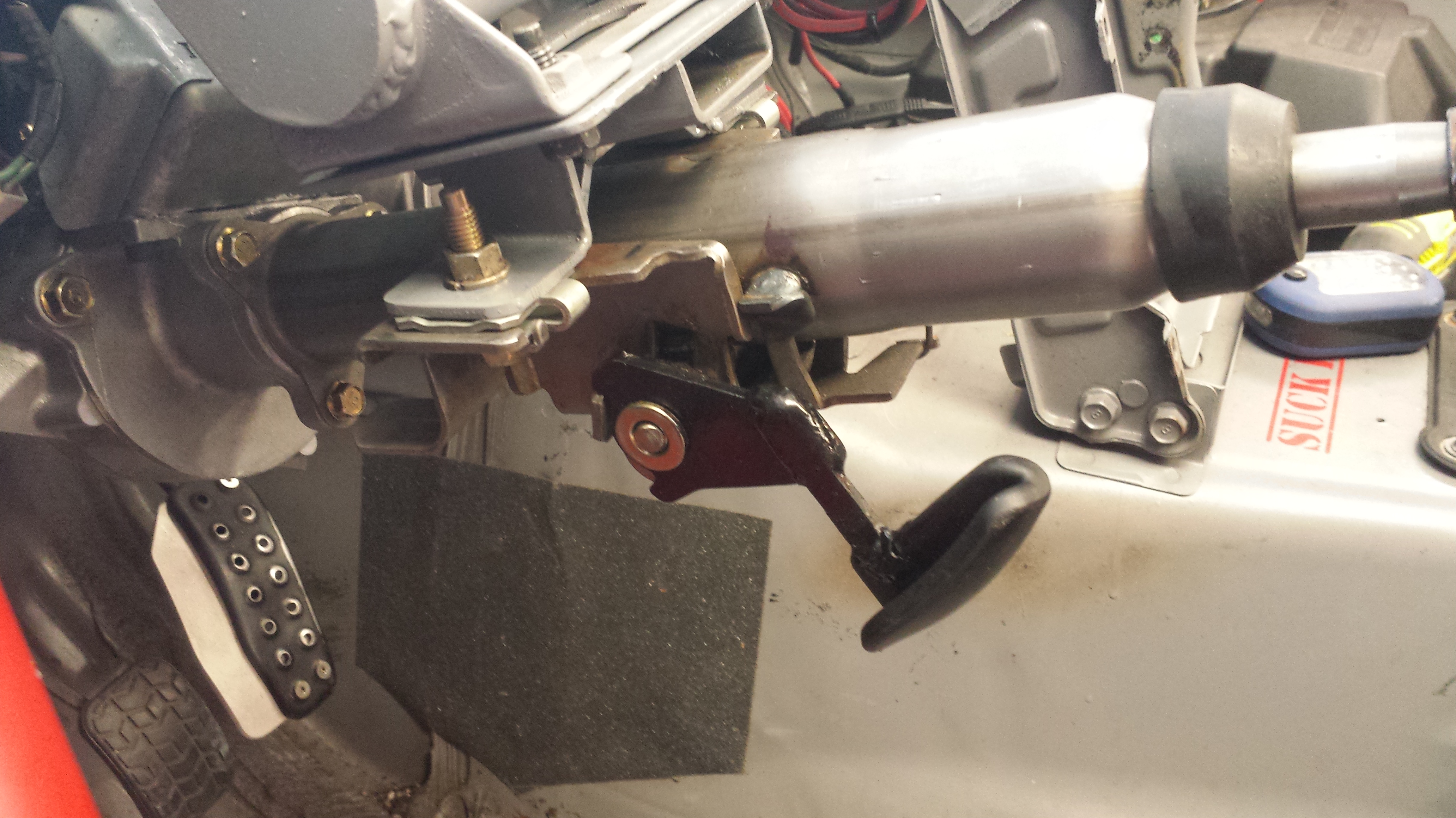
The tilting column adjuster handle is VERY much in the way when climbing around the column getting in and out of the car, so that needed to be modified to tuck it out of the way:
I also went ahead and installed a smaller steering wheel. I went from a ~14″ / 350mm wheel to a 11″ / 280mm wheel. This effectively reduces the arc length that the driver’s hands need to travel to put in the same steering angle by about 25%.
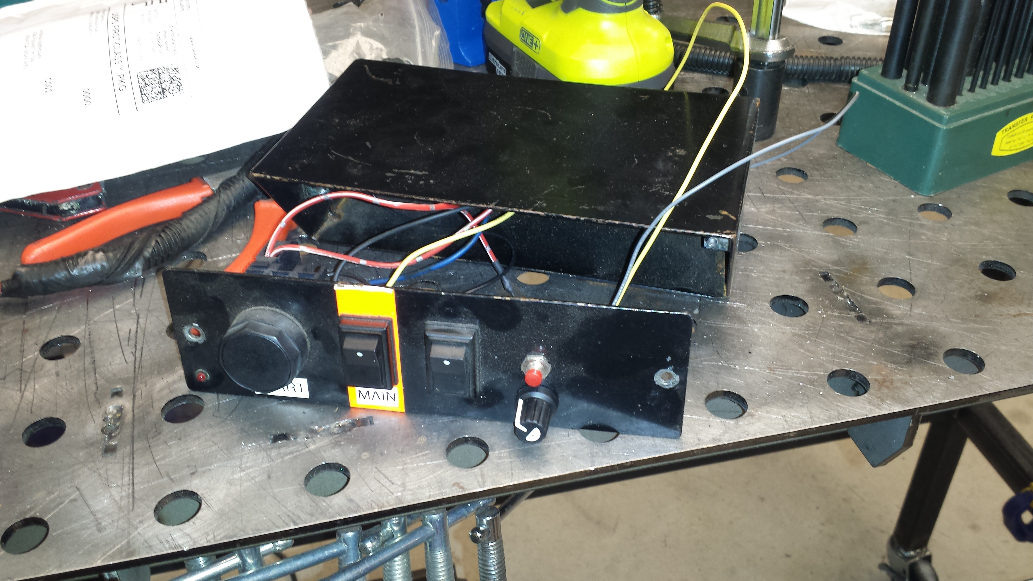
With all of the hardware complete, I could get a start on the electrics. I ran and terminated all of the large-gauge wires that carry power to the motor (that are connected directly to the battery with a 60 amp fuse in line), and started modifying the switch panel to accept the potentiometer. I should be able to put the controller in there as well, to keep it out of the box, and tap into a couple of spare pins in the harness going out of the box to run the controller output to the motor, making for a nice, clean install.
Updated 06/22/2021 to fix broken links due to a website update on EPowerSteering.com
UPDATE: Now that this is done, and has been a huge success, I want to put a quick guide & parts list right up top for reference. This is if you take the DIY route. EPowerSteering.com also sells full ready-to-run (just fabricate mounts for your car) kits:
Compatible Steering Columns:
02 – 07 Saturn Vue
05 – 07 Chevrolet Equinox
03 – 06 Saturn Ion (only in steering column with metal ECU case!!)
Pontiac Torrent
When you order the controller, put a note in that you would like a 10K potentiometer adjuster. Per EPowerSteering.com, the adjustment range on the 10K is much more appropriate for smaller cars. I can attest that with the standard 100K that they ship with, my adjuster hovers around “nearly off”, and the 10K pot will give finer granularity in the lower ranges of adjustment.
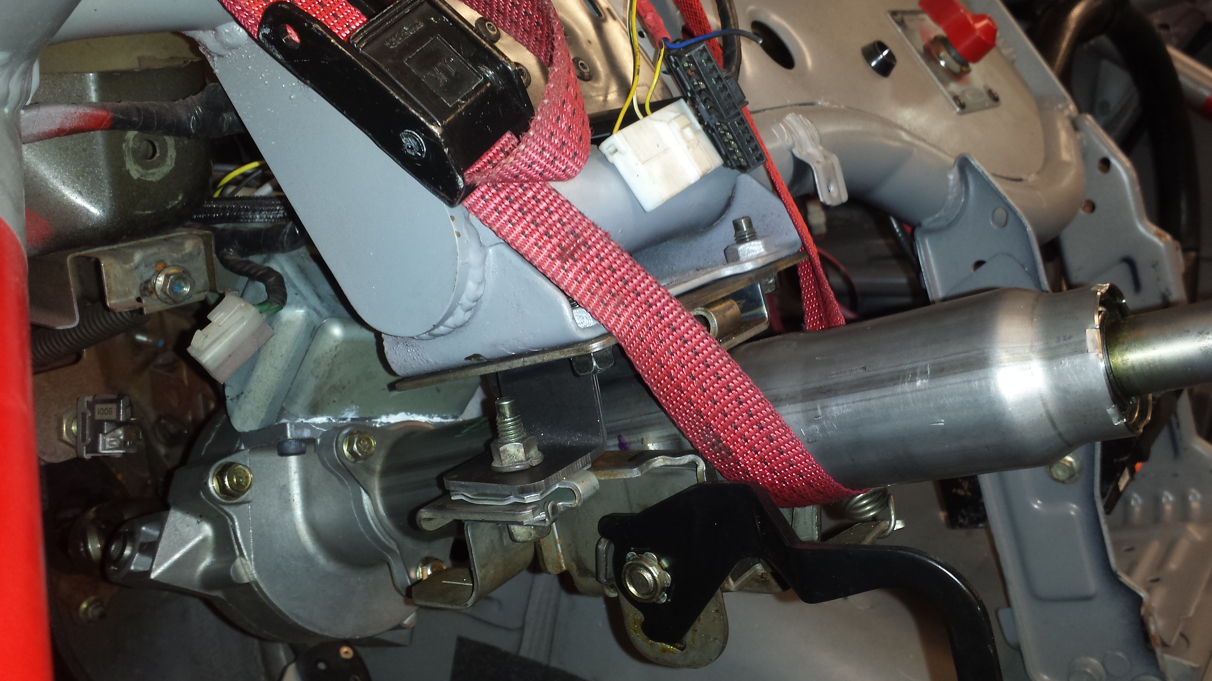
If I have one complaint about the race car it’s that the steering wheel is fairly brutal on the driver. With aero and 9″ slicks going through a Manual rack there’s a ton of feedback. Too much feedback. And because of how heavy it is even with the Manual rack (again, 9″ slicks), I haven’t even wanted to run a depowered PS rack.
Of course, power steering would fix this, but it’s heavy, often messy when they boil over, and saps power from the engine. I already don’t have nearly enough power, so that’s out.
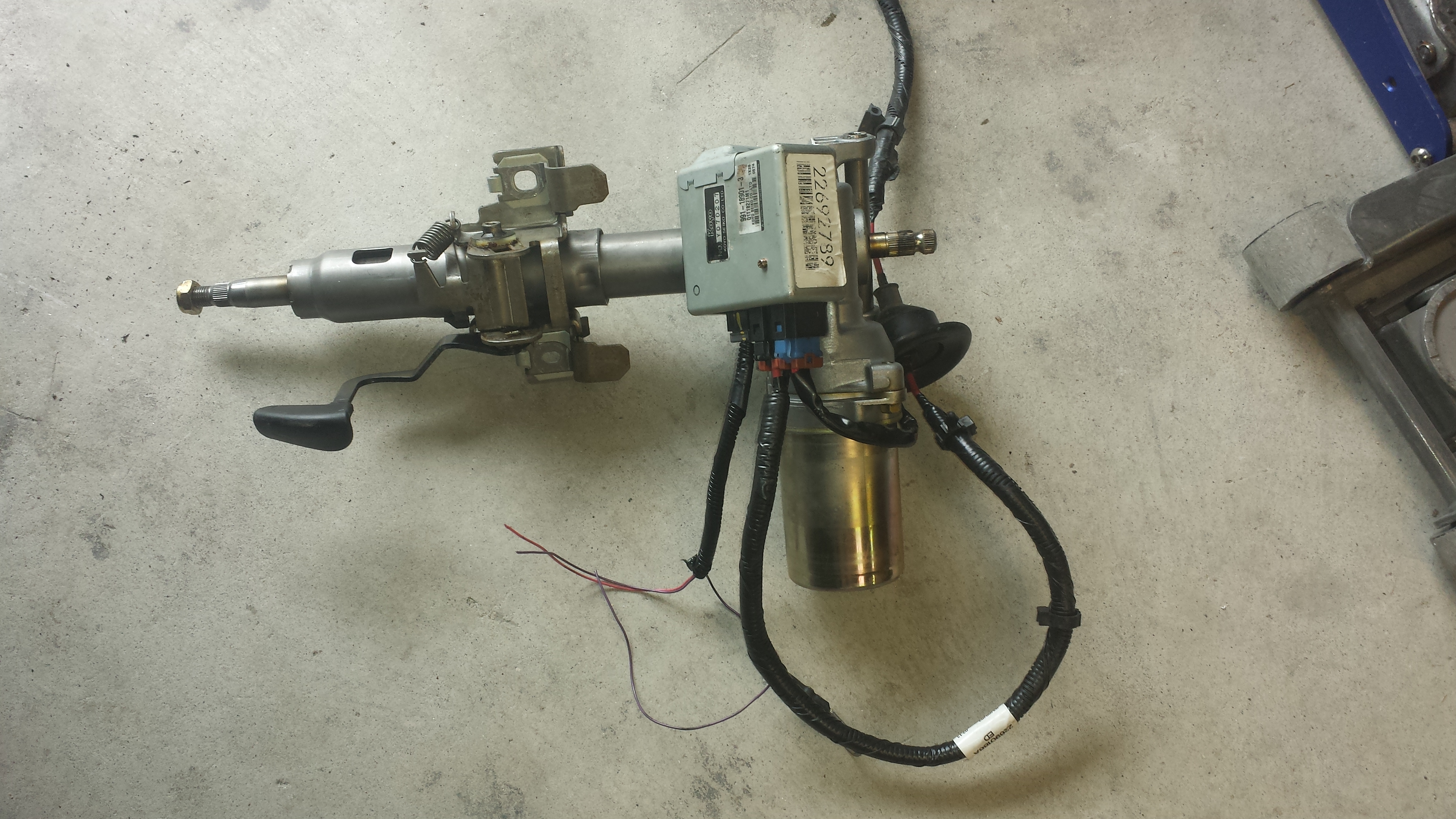
However, I found out recently about a GM electric steering column that’s been seeing heavy use in Rally and other offroad racing disciplines, along with a company that sells a controller that spoofs the CanBus signal, and allows you to adjust the amount of steering assist. I’ve been toying with the idea for a while now, but an autox buddy had one installed in his Ecotec powered Lotus 7 clone and frigging loves it. With some direct experience and some research in the bag, the time came to start building.
So here’s the plan:
-Snag a steering column & controller
-Fabricate mounts and an intermediate “adapter” to go between the end of the GM rack and the input of the Miata’s intermediate shaft. I want to keep it as bolt-in as possible in case something breaks and I need to swap stock parts in.
-De-Power and refurb the PS rack I’ve had sitting on the shelf for ages now waiting for its moment to shine. With the power steering, adding in the faster rack would be good. I’m going to pair this with a smaller steering wheel to lower the distance my hands will need to travel on the wheel for a given angle of input.
-Add steering rack travel limiters to prevent the 15x10s rubbing on the sway-bar in paddock / grid / during big spins.
The steering column in question is out of the Saturn Vue & Chevy Equinox, and is a little over 3″ shorter than the stock NA steering column. I went to the local Pull A Part and snagged one out of the yard, along with the full wiring harness. The nice thing about this column is that they’re built for far heavier cars than what I’m putting it into, so it should be plenty. This system has seen extensive use in the offroad racing community, and I’ve seen them installed in things between ride-on lawnmowers and Unimogs. It appears to be insanely versatile.
To get everything lined up in the right place took a lot of careful measurement. It doesn’t need to be micron-perfect, but within 1/8″ or so is the goal.
The mounts are within an inch or so of where the Miata’s mounts are, so I’ll be able to use the stock upper mounts points (using a modified stock column mount), and will need to re-engineer the lower mounts. The plan is to weld brackets onto a stock upper column mount, and cut the lower mounts off of a sacrificial stock column.
Overall, the GM column is about 3″ shorter than the stock Miata column. This is a good thing as it will allow me to get the steering wheel in a stock location without having to modify the intermediate shaft that runs between the column and rack.
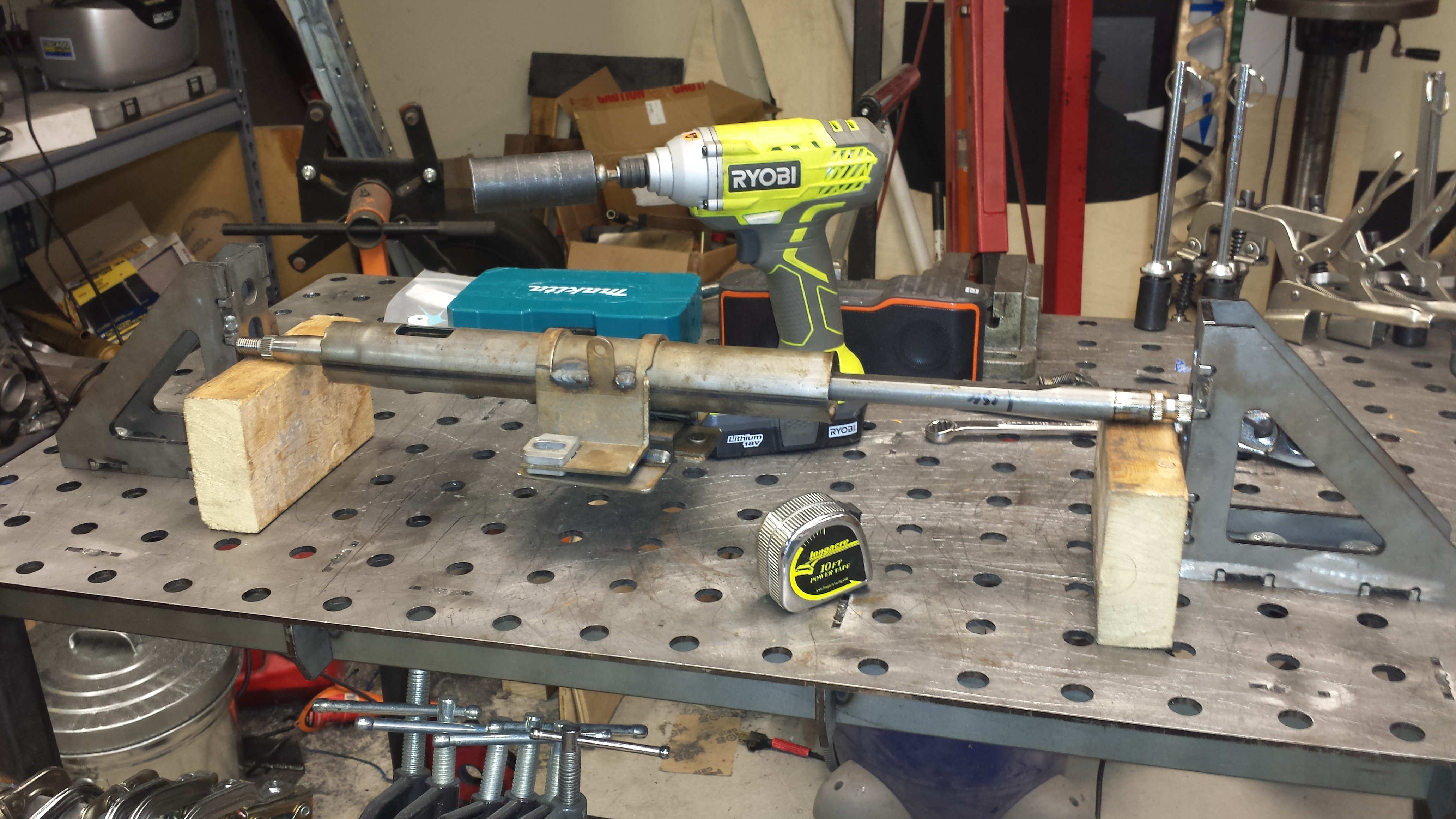
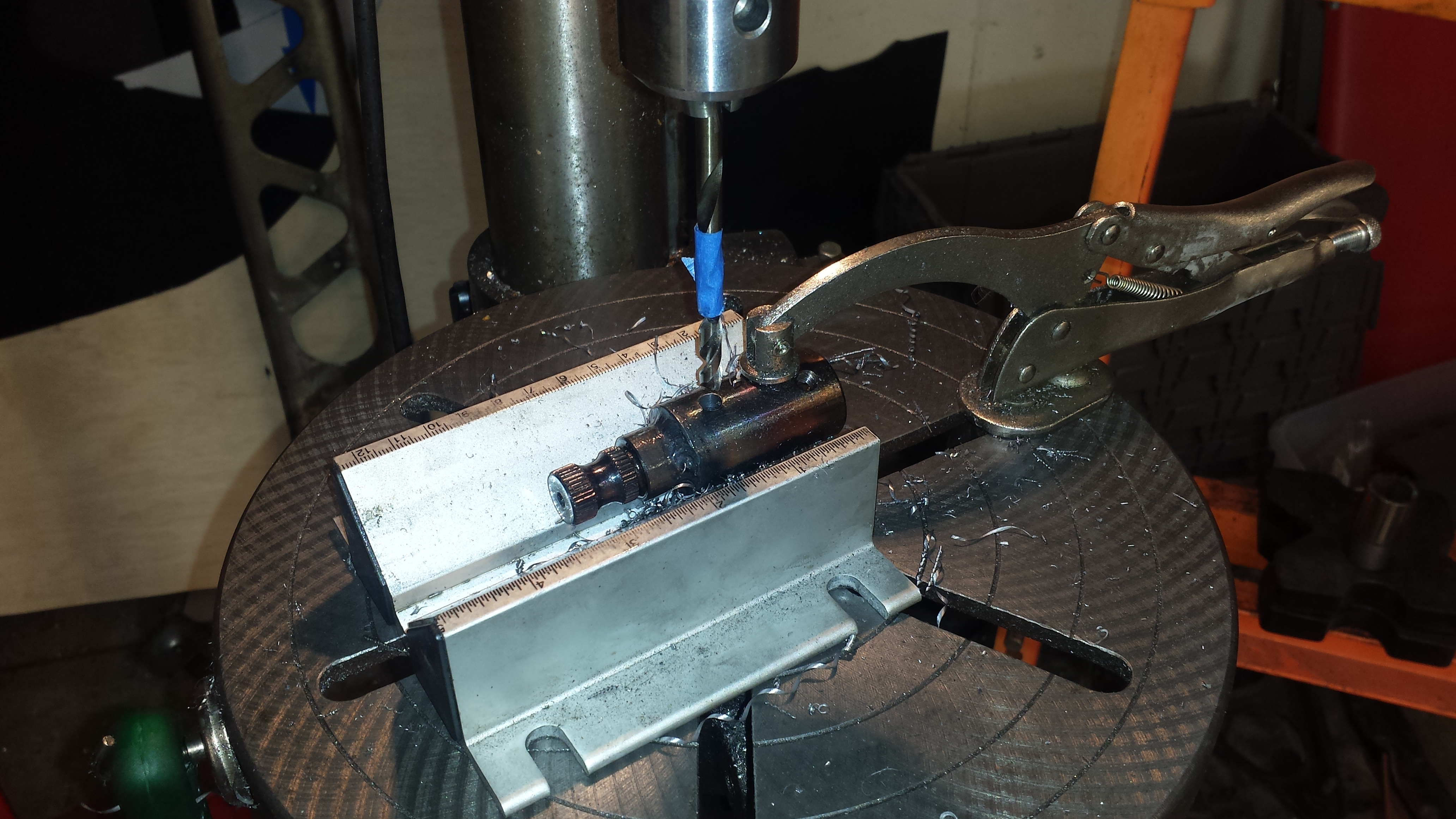
After disassembling the sacrificial stock Miata steering column, I discovered, much to my amazement, that the lower section (where it bolts to the intermediate shaft) is 3/4″ diameter. And just about every aftermarket steering component out there is 3/4″. Due to that size being ubiquitous, EPowerSteering.com sells a 16mm spline to 3/4″ shaft adapter. I’ll use that and a section of the stock steering column to build a small adapter that will spline / bolt onto the bottom of the GM column, and spline / bolt into the stock intermediate shaft.
I took the parts to a buddy’s shop where we cut the stock steering column down to length, and TIG welded the parts together. It could have been MIGed, but with the threads and fine splines, I wanted to avoid spatter at all costs.
After it was welded, I drilled and tapped through the adapter and spline stub to run a bolt to serve as a failsafe in the event the weld breaks, as that weld essentially is a single-point-of-failure in the steering system.
With the column setup complete, it was time to start fabbing the mounts in the car.
The response I got from the setup stand build has been tremendous. Several folks have suggested that they’d like plans be made available so they can build their own set, and that they’d be happy to throw a few bucks my way for the time that went into developing them. I’m staggered, because I thought I’d make a couple sets for buddies and that would be it, and that would be that.
The directions include a materials list, a cut list, some 3D modeling and photographs of the stands.
Chances are that, having built a few sets now, I may have left out a few things that seem intuitive to me just from having done it several times. Let me know if you have any questions and I’ll do my best to answer them.
If you’d like the plans, e-mail me at amaff5@gmail.com and I’ll send a .PDF with the plans.
This is very much a hobby for me, not a business, and these are super useful tools for “us people”. I’d rather more of my racing buddies have access to them than not, so I’m making the plans available for free. Hell, if we had money to burn we’d just spend $2,000 on the commercially available options and be done with it.
That said, I have put a great deal of time and sweat (omg so much sweat you guys) developing these. If you feel that these were worth it and / or want to throw a few bucks in the hat / Tire Fund for the R&D done on these, you can do so here:
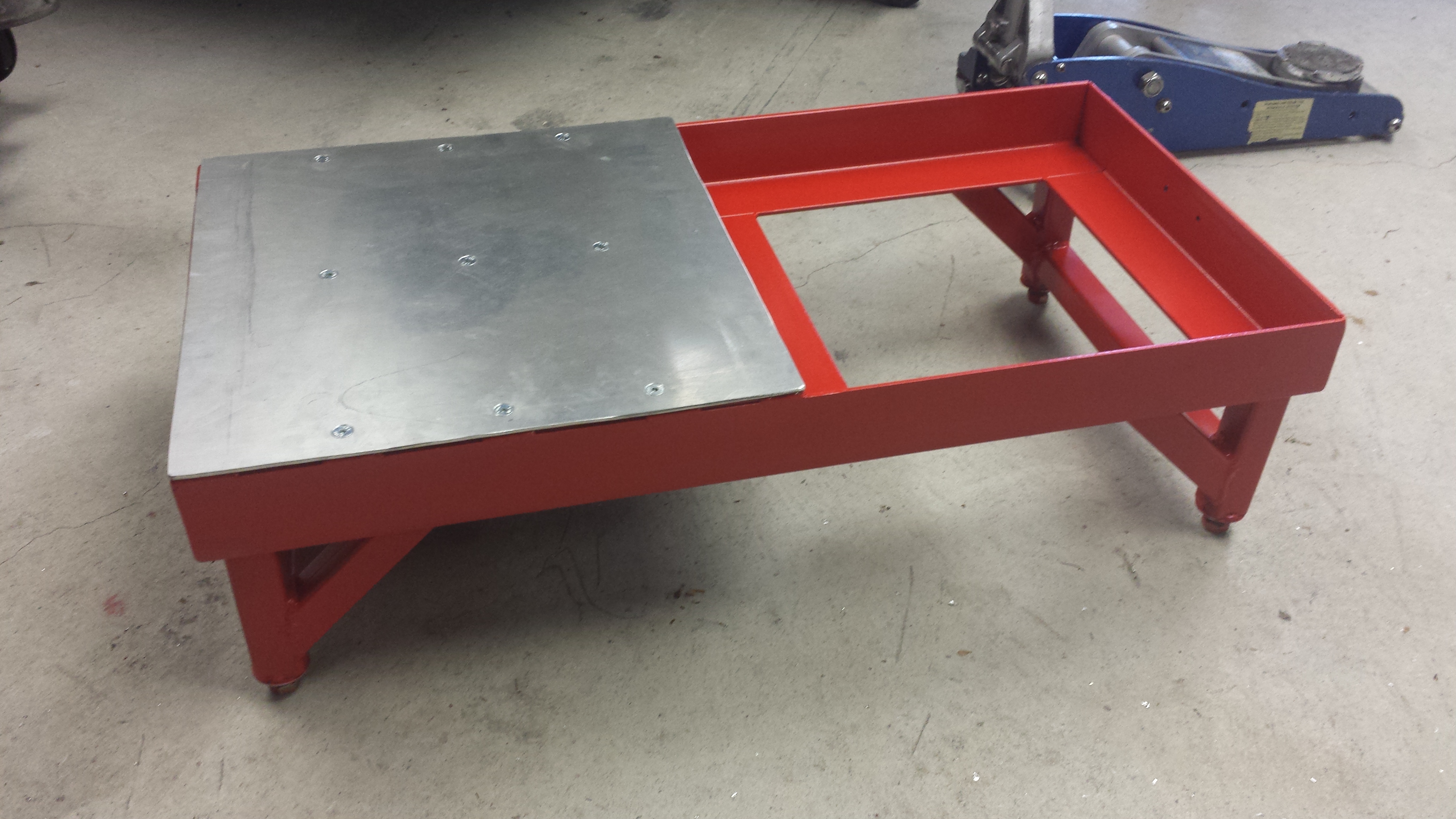
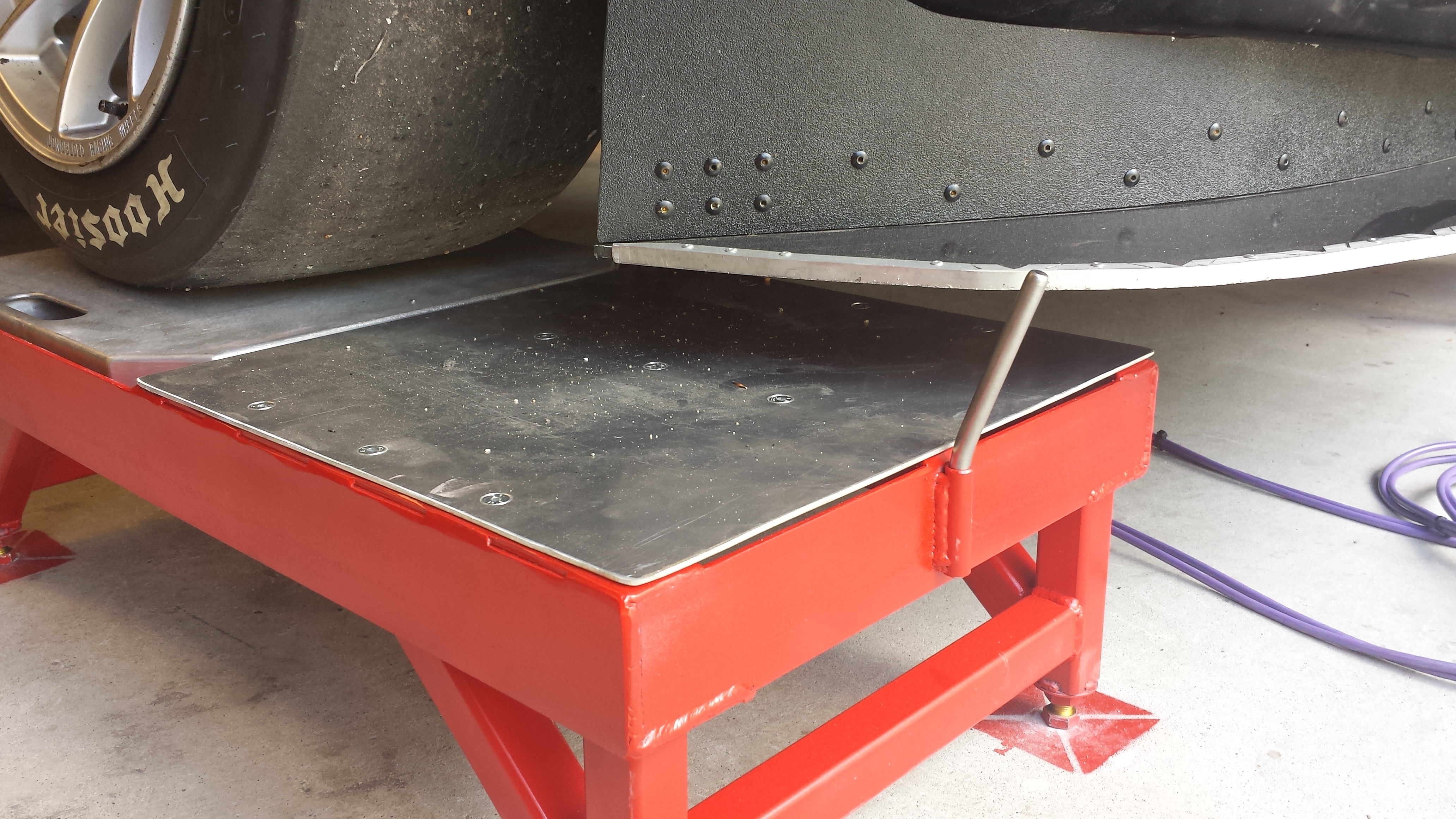
Roll off pads are very useful for setup, allowing a place to make alignment changes, to zero the scales, and to allow the tire to roll to undo any bind that setting changes may have introduced. They are also the thing that adds a TON of cost to the commercial setup stand options.
Since I’m fully committed at this point, might as well go big.
The pad itself will be a piece of 1/8″ aluminum sheet, supported on both sides and in the middle.
The side supports are made of 3/16″ steel bar with 3 holes per side drilled and a nut welded to the back side on each to secure the plate. The bars are supported on 3 sides, sitting on the frame on the short sides and 1 long side. Those bars on top of the frame puts the floor just a shade lower than the scale pads, allowing space for some thin grease plates to do alignments.
The center support is a length of 1″ bar with 3 holes through it. 1/4″ on one side for the bolts, and just about 1″ on the bottom to allow a 10mm socket with an M6 nut to be inserted from the bottom.
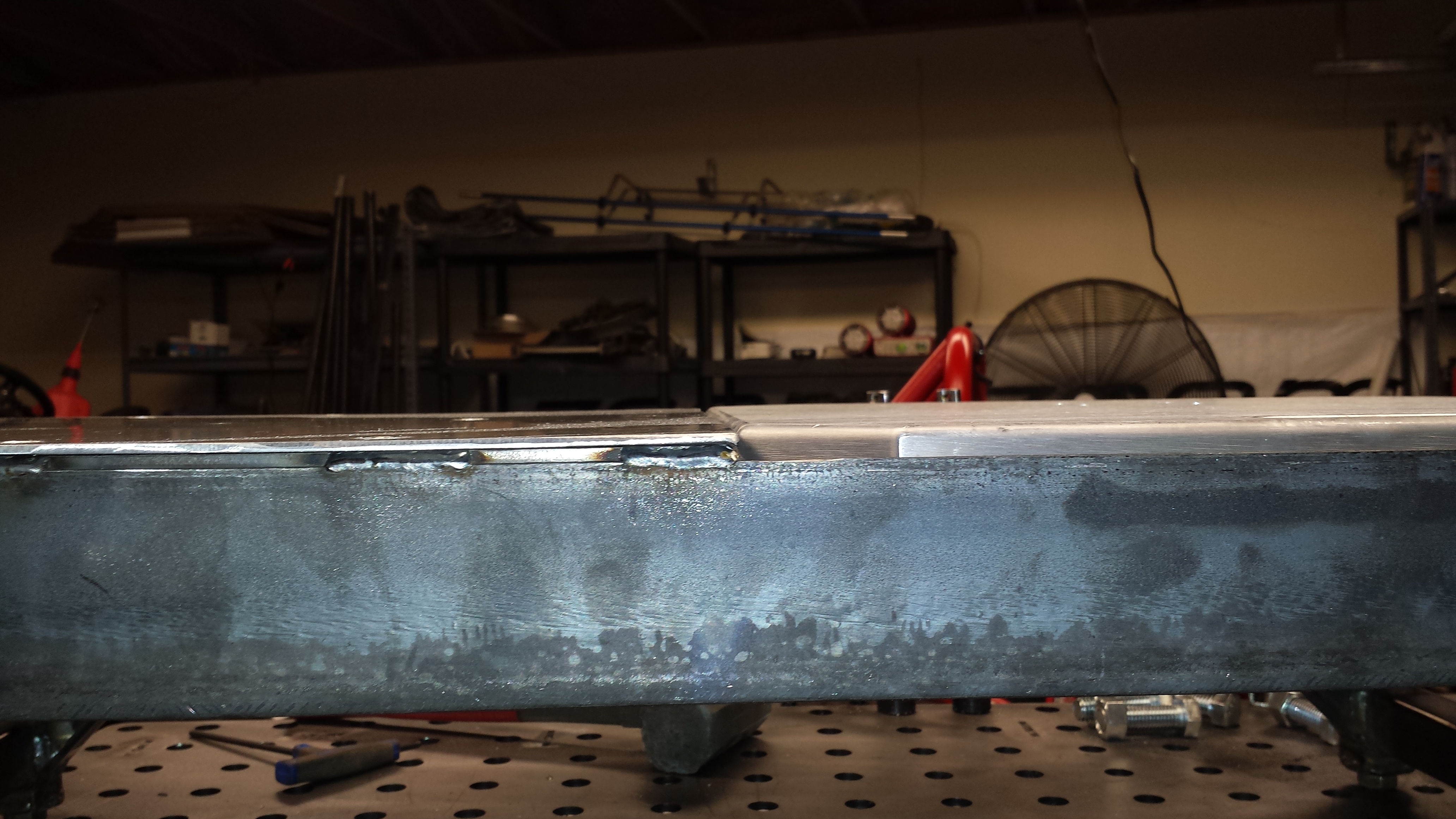
Once the 2 sides were done, the next challenge was fitting up the middle support tube such that it was dead level with the 2 sides so the floor is perfectly flat. To do that, I flipped the entire frame so that the side-supports were flat against the welding table, then placed the tube in to get tacked up so that the welding table top became the reference surface for the whole setup.
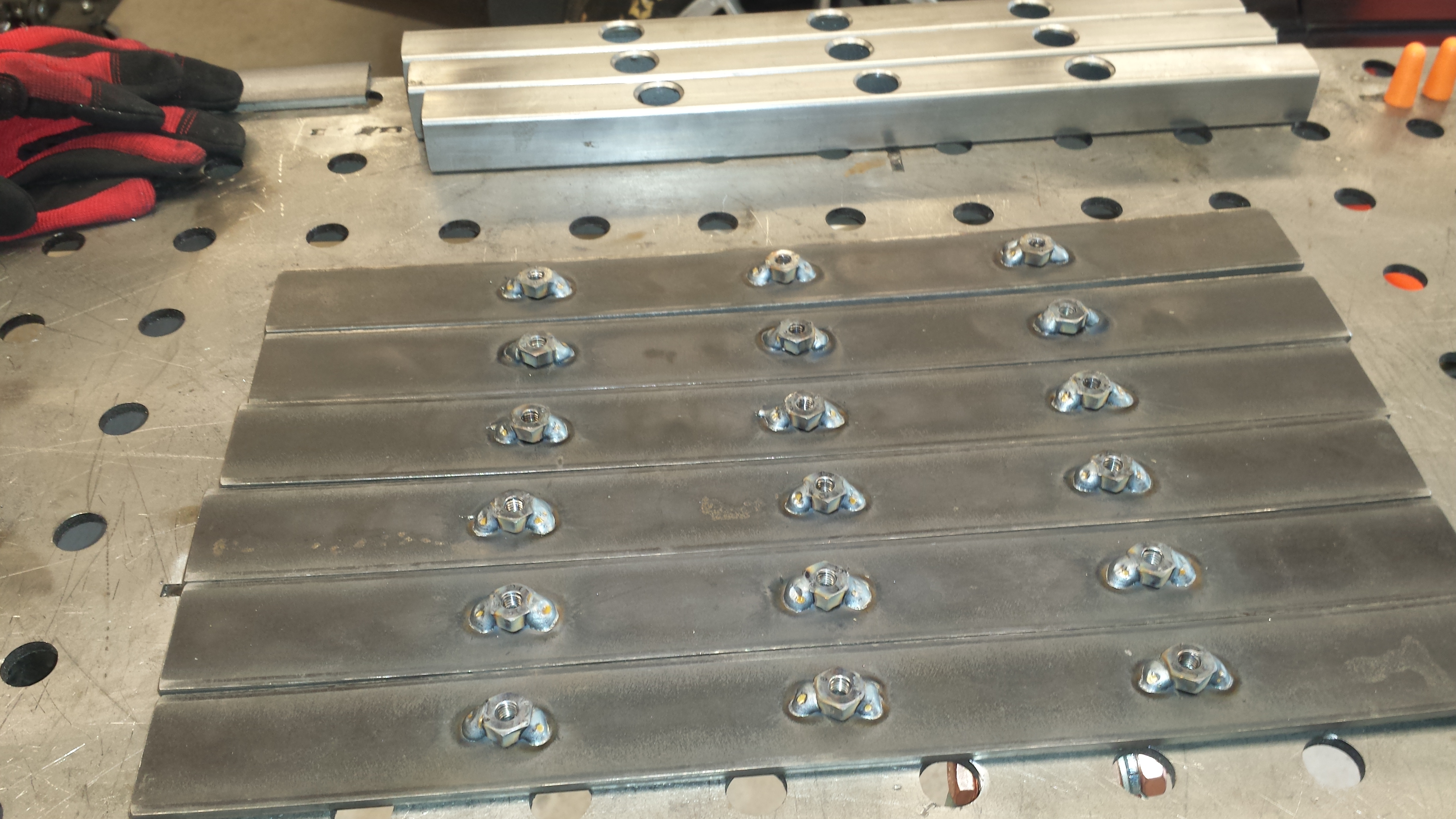
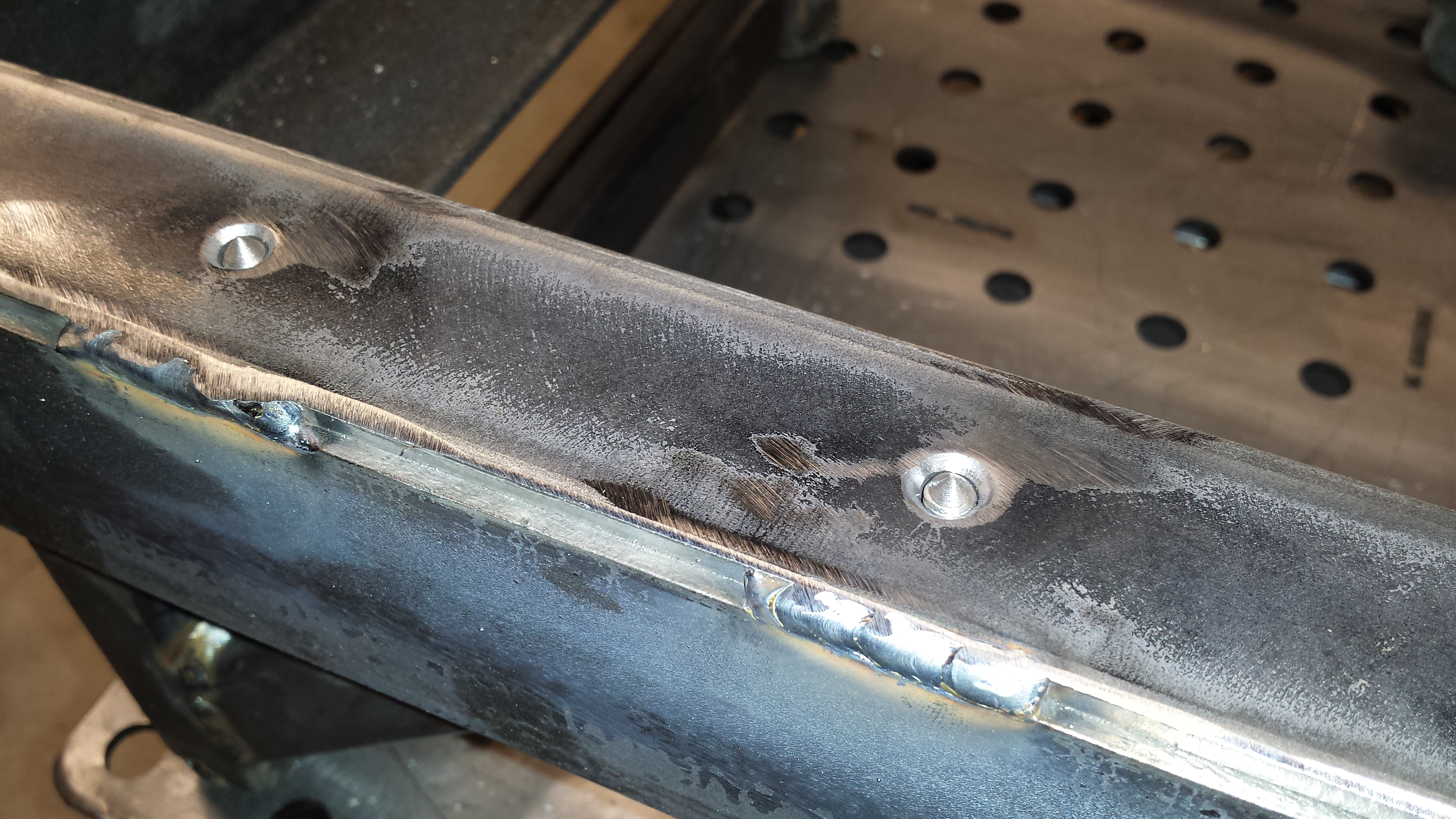
With the frames completed, it was time to fab up the floor. After rough-cutting it, clamped it to the frame and drilled the 3 central holes as they can be accessed from underneath. The challenge, however, was to get the position of the 6 holes on the sides that were covered up by the angle iron.
This is where a DILYSI Dave hot tip came in incredibly handy. Long ago when I was building the new Seat Mounts, he suggested making some blind transfer punches out of some bolts. I made up a few more so I’d have a full set for this job. I threaded them into the holes, then bolted down the 3 central bolts so that the floor would be in the correct place, then gave each location a sharp whack with a rubber mallet to mark its location on the aluminum sheet for drilling.
With the prototype nearly complete, I wanted to do some strength testing (ie: dropping the car on it vigorously a few times) to make sure there weren’t any glaring issues:
And since I was painting the new Saw Stand, I figured I might as well hit this one with a coat of paint. This, it would turn out, would be a mistake.
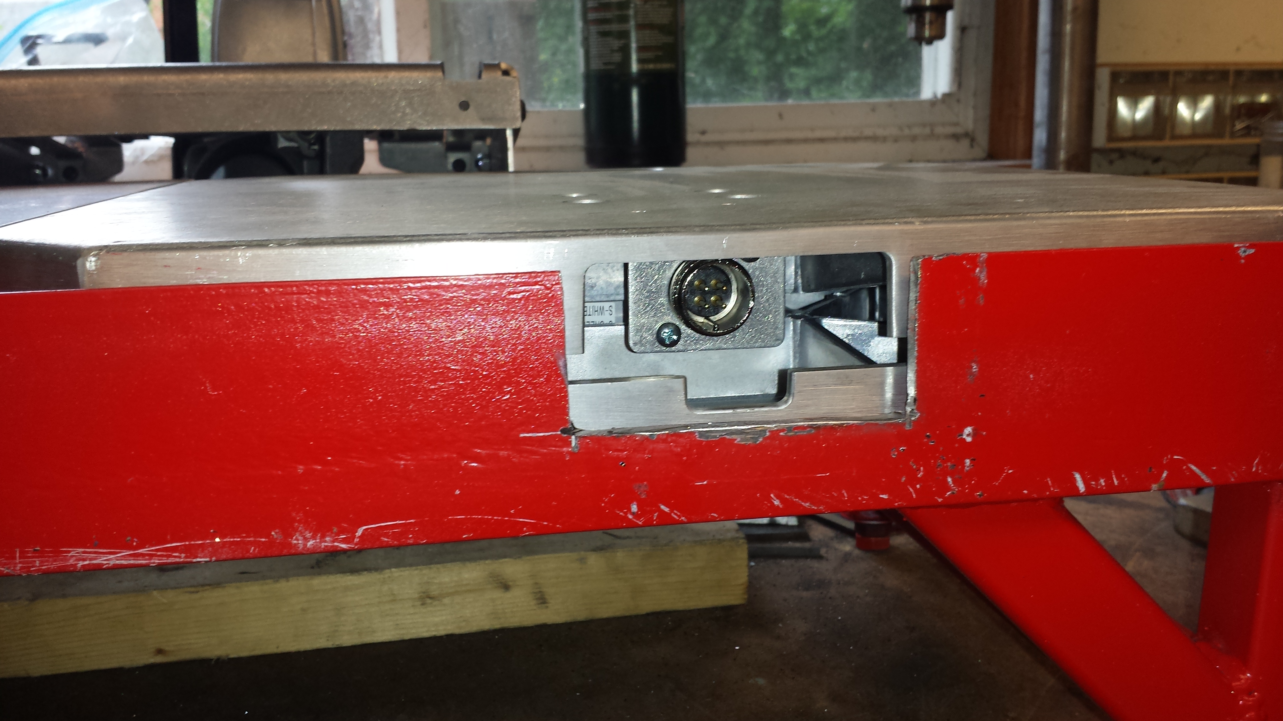
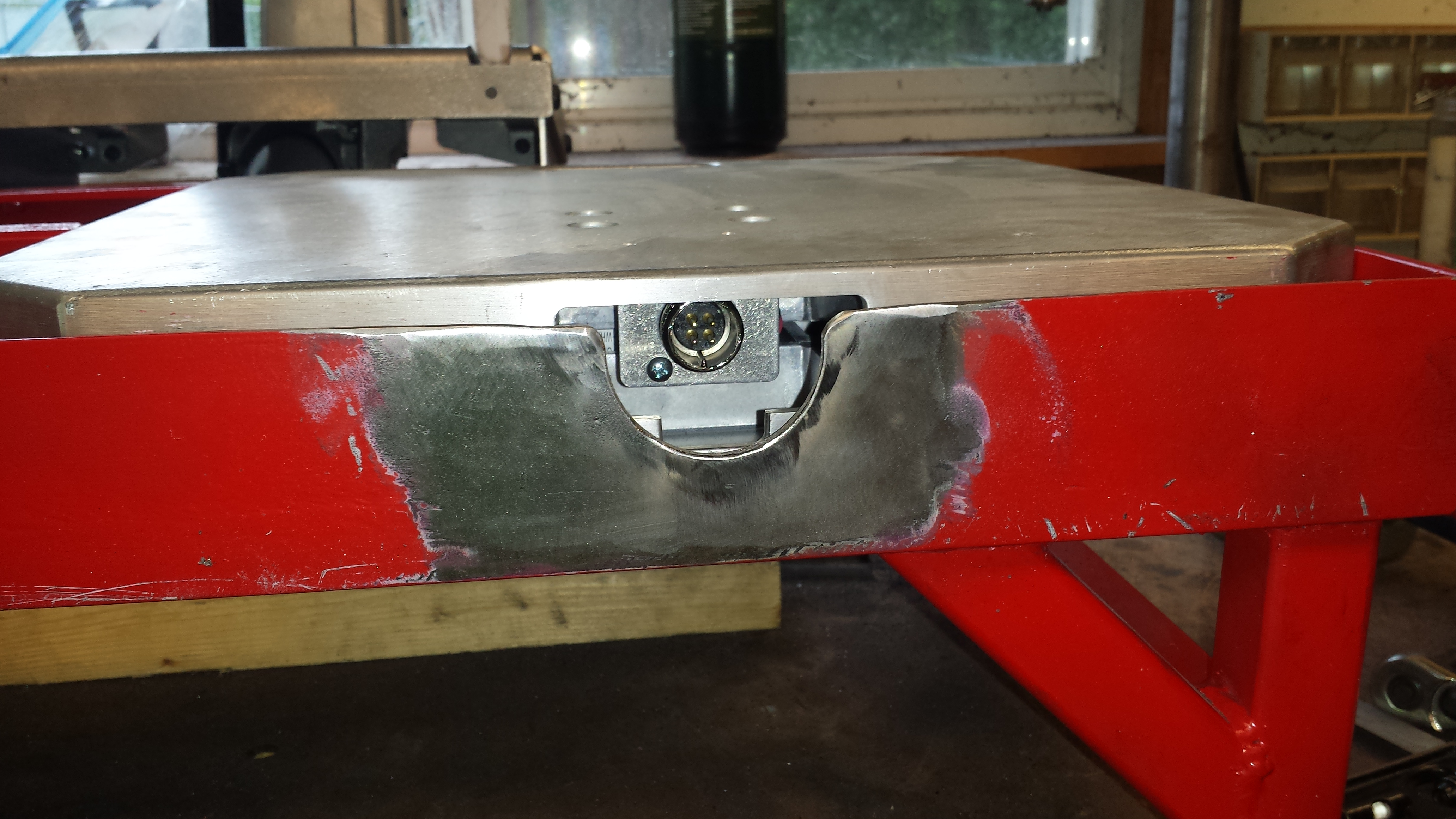
The keen eyed will notice 2 glaring omissions at this point (the point at which I thought I was done with this…). 1. There is no provision for the cable for the scales to pass through, and 2. There are no wheel stops. The commercial ones don’t usually have wheel stops, but they’re much shorter so were you to roll the car off of them, the likelyhood of them damaging the car is fairly low. These are very tall, and VERY strong. As such, should the car roll off of these, it would be ugly. I’ll address these next.
First up is a notch for the cable. Attempt number 1 was…. well… fugly. I tried doing it with and angle grinder and the results were bad.
It was at this point that the true value of a welder came into play. That was ugly enough that I decided to un-cut steel.
After a rethink and some consultation, I decided to use a hole saw instead. Normally this wouldn’t be a problem, however at this point, with the frame fully assembled, it was a bit late in the game. This is by far the dumbest thing I’ve ever chucked up in the drill press, but damn if it didn’t work!
(I’ve no idea why this photo shows up sidewards. Click the picture for the right-side-up image)
Thankfully the results were most excellent. After a little cleanup of the sharp edges and corners with a flap disk, I was very happy.
Now that I know where the notch needs to go, subsequent cuts were FAR easier.
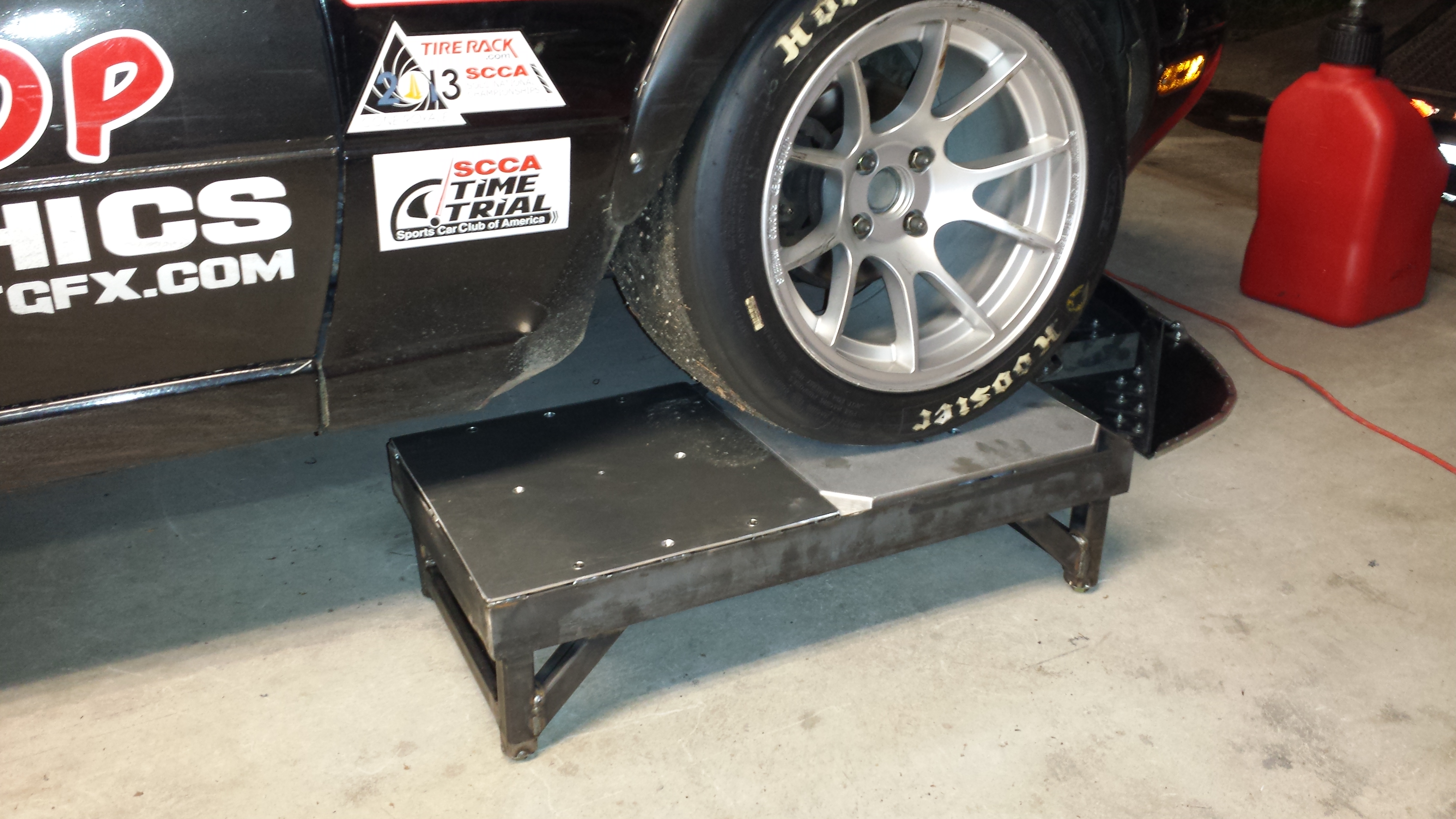
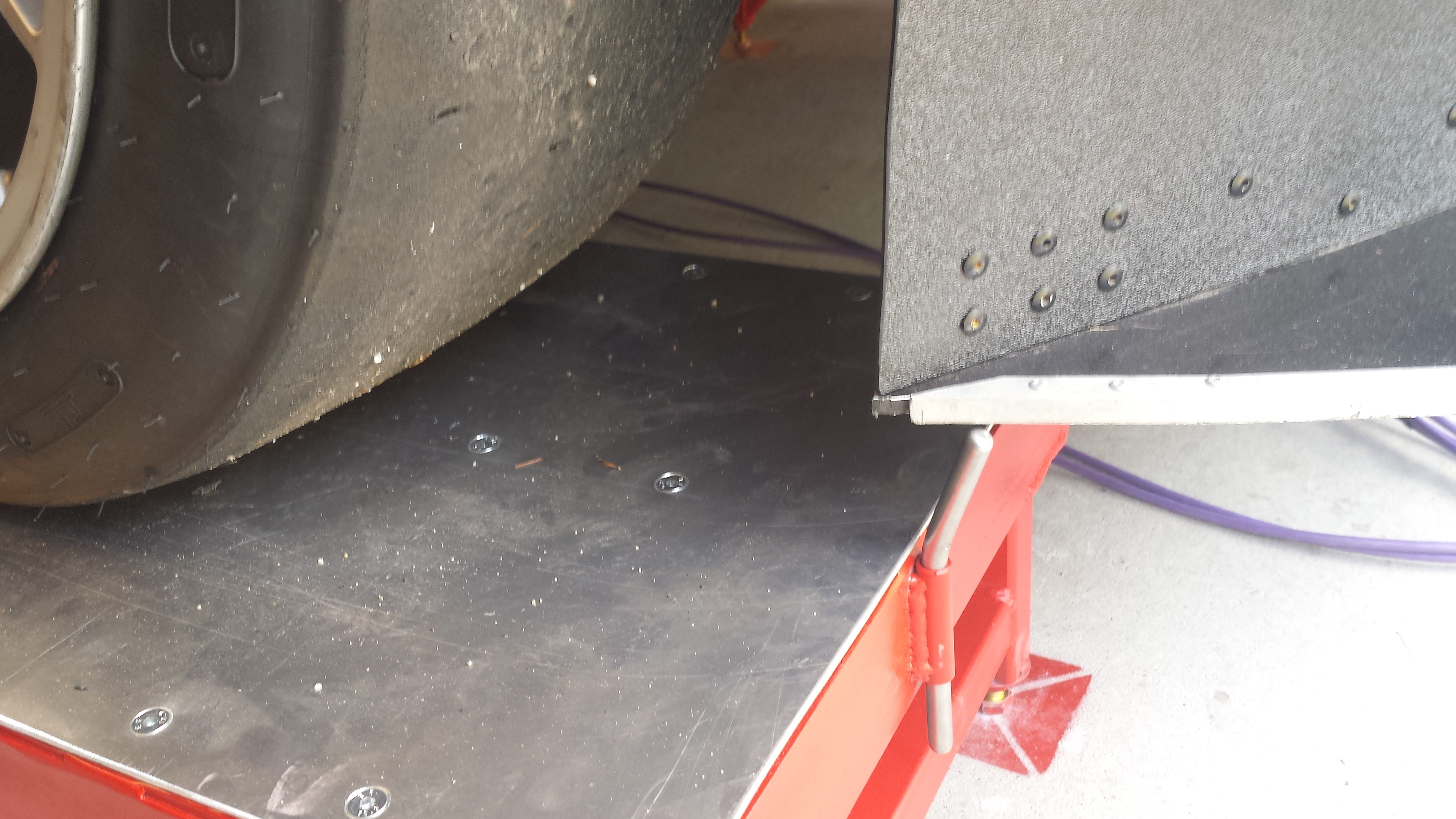
On to the tire stops. After a bit of figuring and evolutionary engineering, I ended up with an easy to fabricate, dead simple solution that will 1) stop the car rolling off the ends, and 2) still allow the stands to stack together to minimize the space they take in the shop.
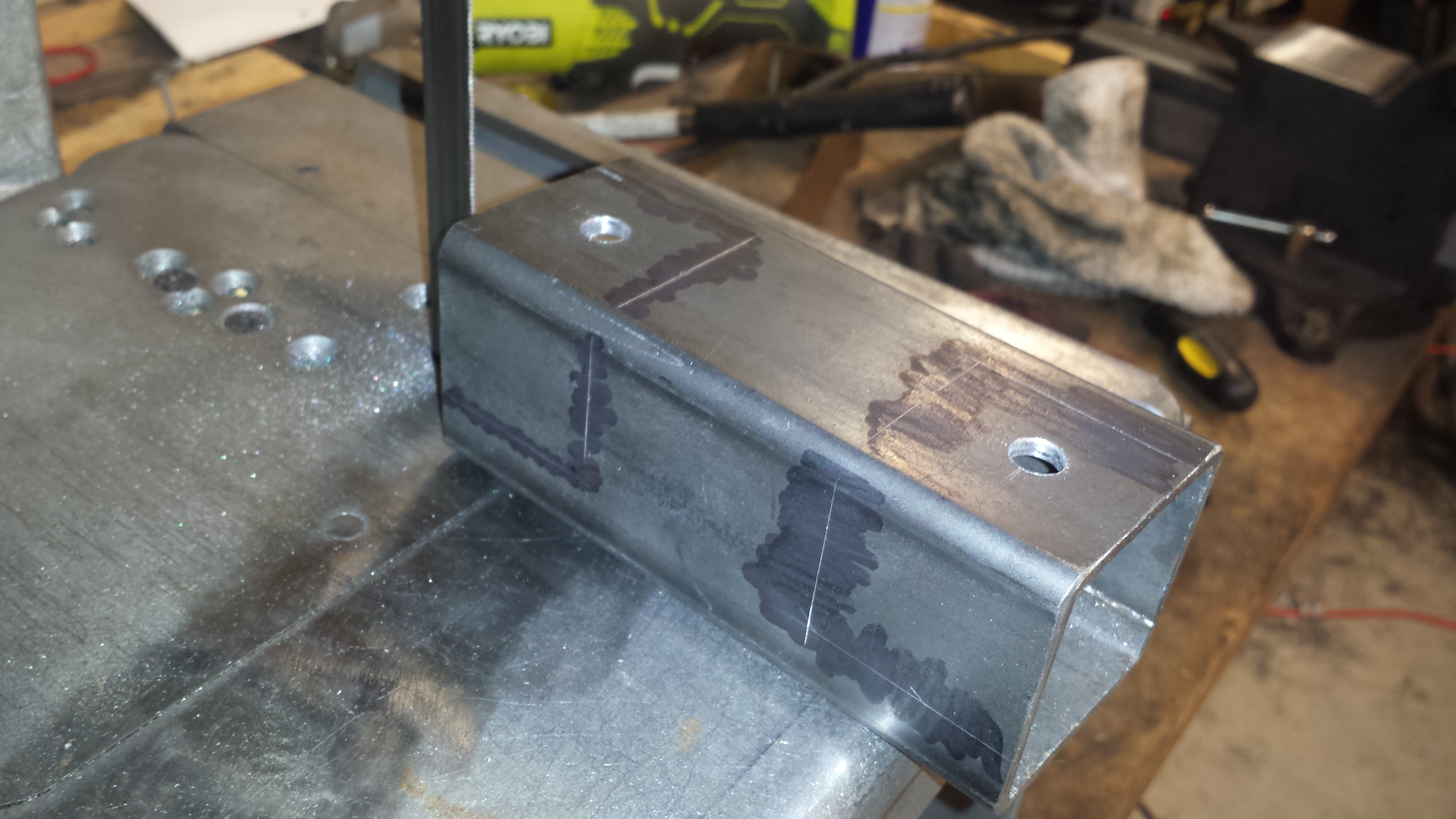
Part the first is a 2″ length of 1/2″ OD tube welded in the center of each end of the frame:
Next is a 6″ length of 3/8″ steel rod, with a bend around the 2″ mark and a bullet nose ground in on each end. The bend is so that they won’t just fall through the tube, and it leaves a ~4″ step that would take an immense amount of force to get the tires over. If you figure out a way to do that, you do your alignments far more aggressively than I.
The short side / long side has an added advantage that I wish I could take credit for but in reality was a complete, but happy, accident. Up front, that long post interferes with the splitter when rolling the car back and forth between the scale and the roll off pad.
With it flipped upside down, there’s still plenty of a step to stop the car (plus the taller sides are still up at the rear), and the splitter clears easily. I love it when a plan, accidental or otherwise, comes together!
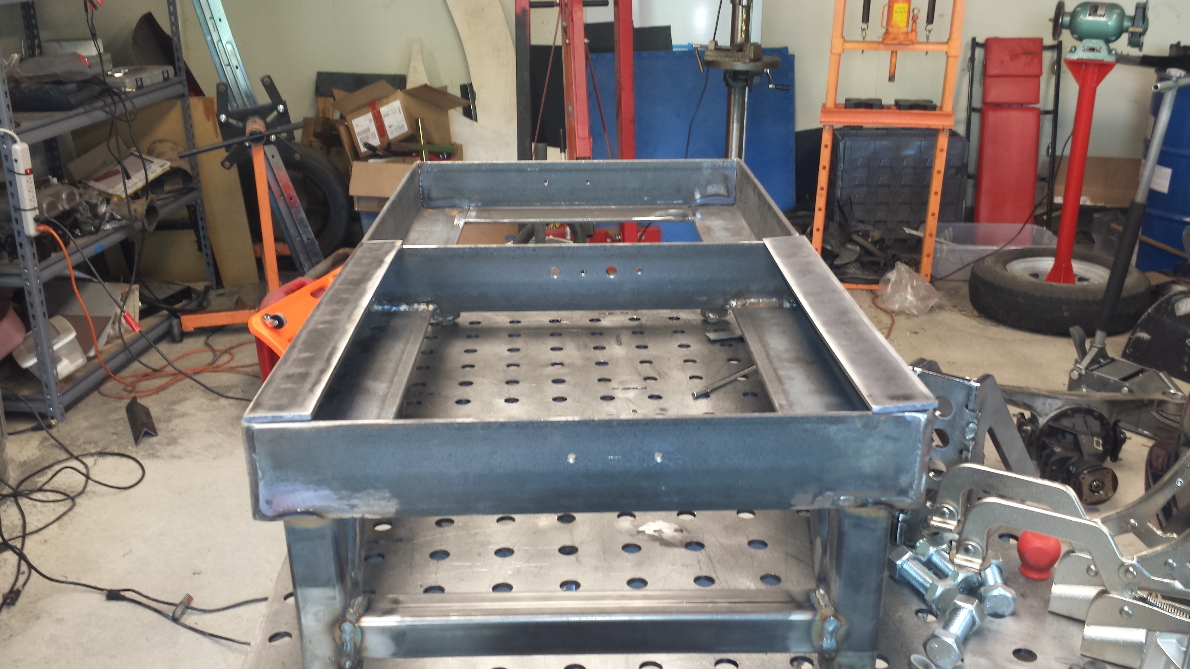
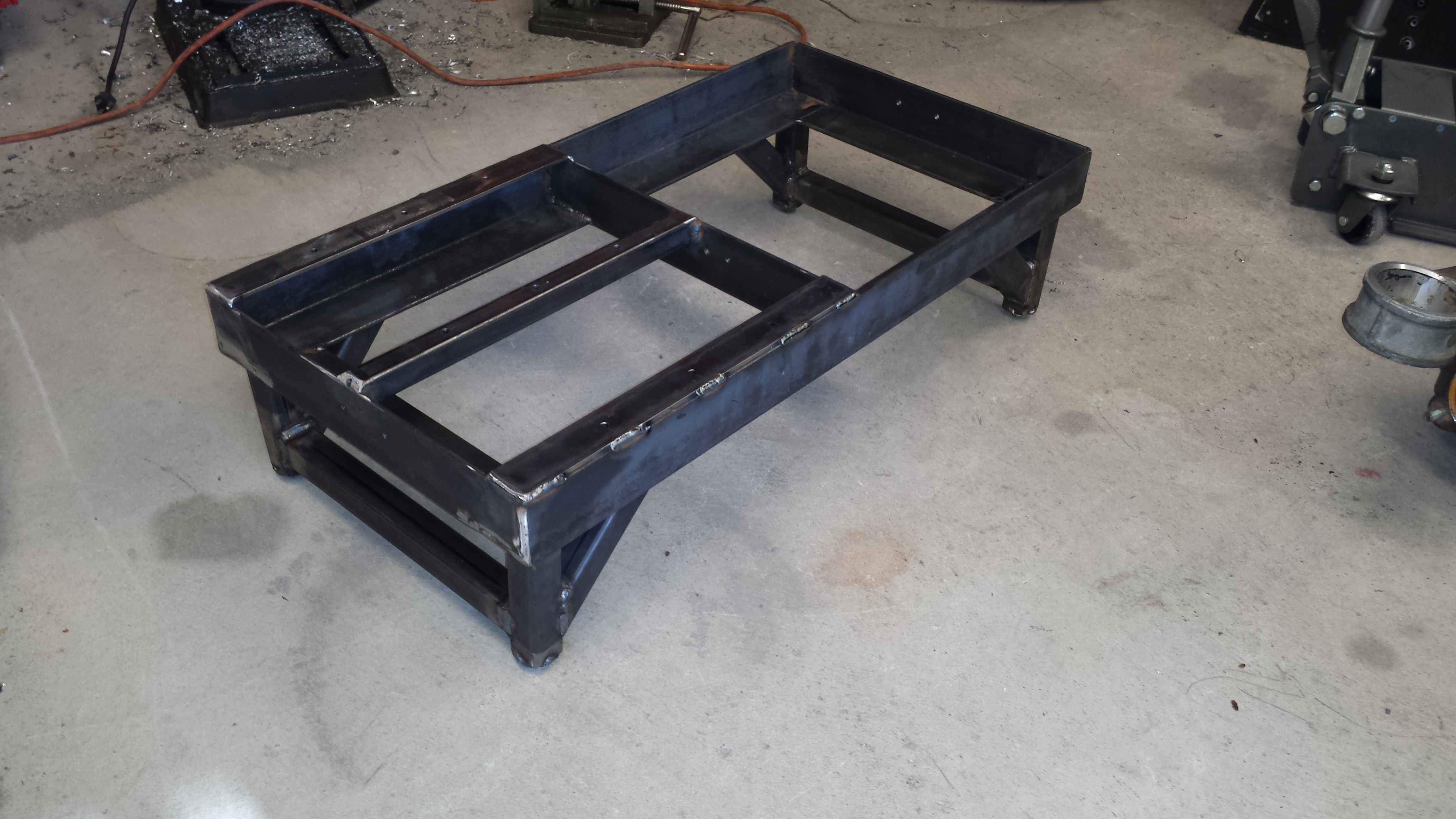
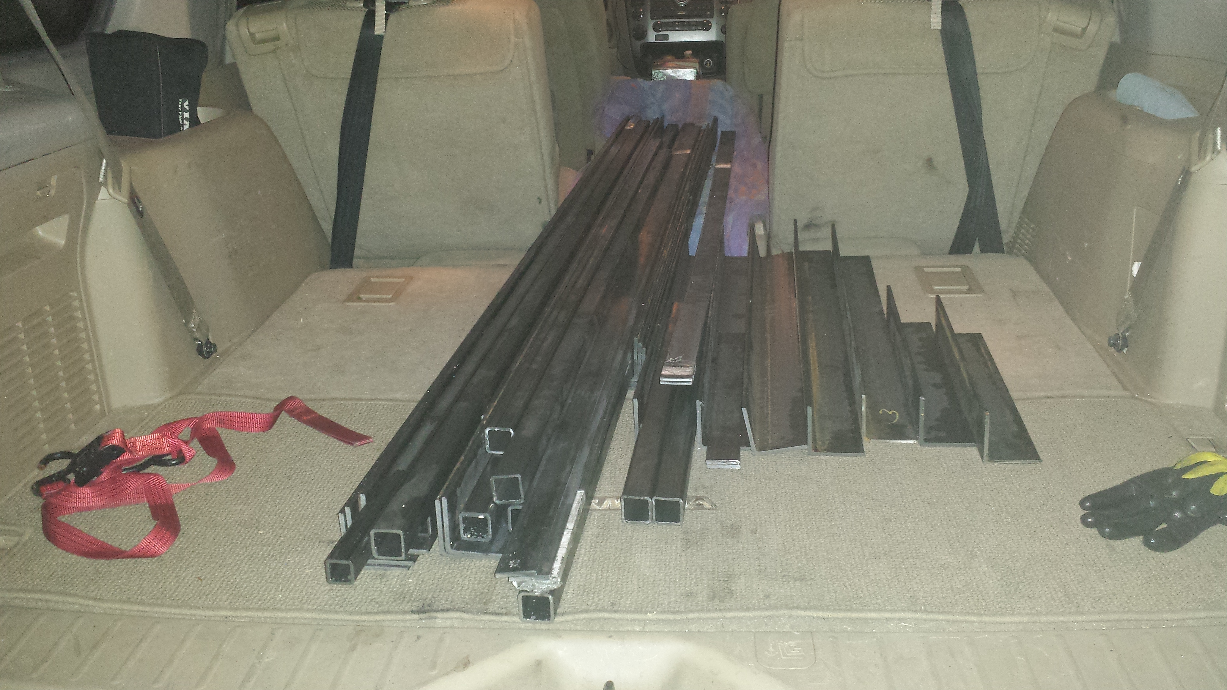
Many moons ago, a buddy posted a few pictures to Facebook of his car on some setup / alignment pads. My curiosity piqued, I reached out and got a bit more info from him, as something similar would be phenomenally useful. I’d looked at commercial options for these, but they are prohibitively expensive, and John’s homebuilt pads looked pretty close to what I wanted for a lot less money.
After a great deal of figuring and bouncing ideas off of engineer friends, it became clear that a set could be made that would also incorporate setup scales, for relatively little cash (and a great deal of time….so, so much time). Initial designs were drawn up and steel ordered.
What follows is going to be a boatload of photos of various stages of the build. It was a very very long process of evolutionary engineering and problem solving, but now that I know how to build them, additional sets will be made relatively (and it is very relative, because they’re a ton of work) easily.
First step: getting a bunch of steel home. I had various pieces cut more or less to length, as I didn’t know exactly how they would go together but had a general feel for at least what the long legs needed to be. The rest were cut to fit in the back of the truckster to get it home.
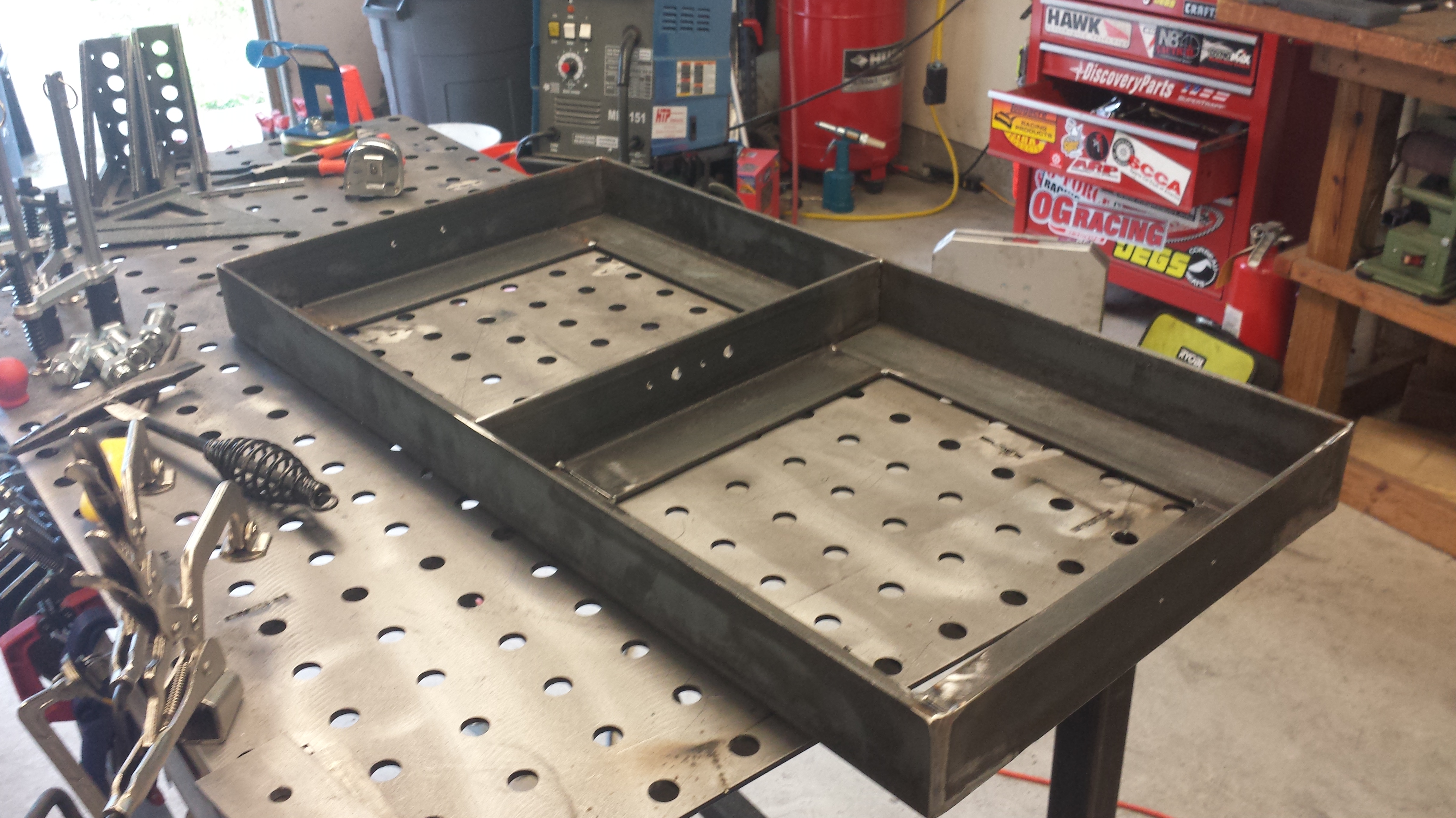
Lots of measuring (way more than twice), cutting, coping and beveling later, and the first frame was roughed out.
The scales will sit on the side with “floor” on all 4 edges, and the rolloff pads will go opposite them.
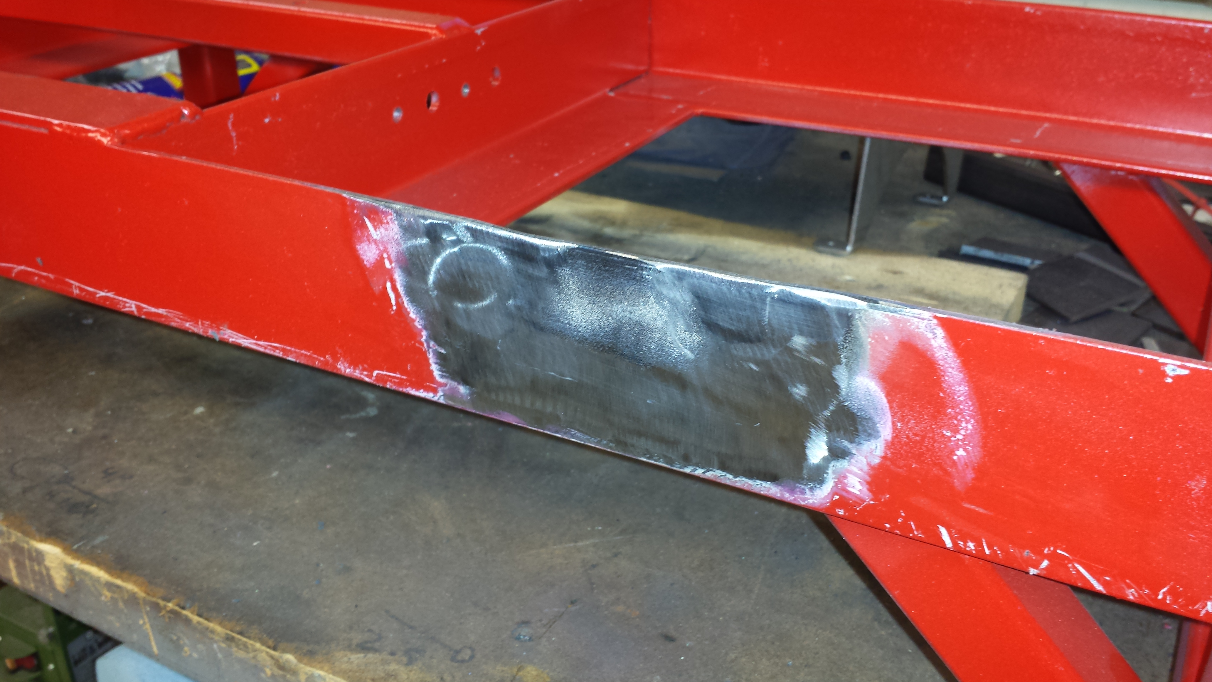
Cutting 45 degree miter joints would have been far easier from a fab standpoint. However coping the joints has 2 very big advantages: it leaves nice, flat areas on each end of the “long” side of the frame for the legs to sit on, and with that, there is a lot less strain on the welds and puts everything in compression, with the welds mostly holding the pieces together, and not supporting the weight of the car.
It’s not that I don’t trust my welds, but with something that needs to hold the weight of a car from crushing me to death, I will take every bit of added strength I can get.
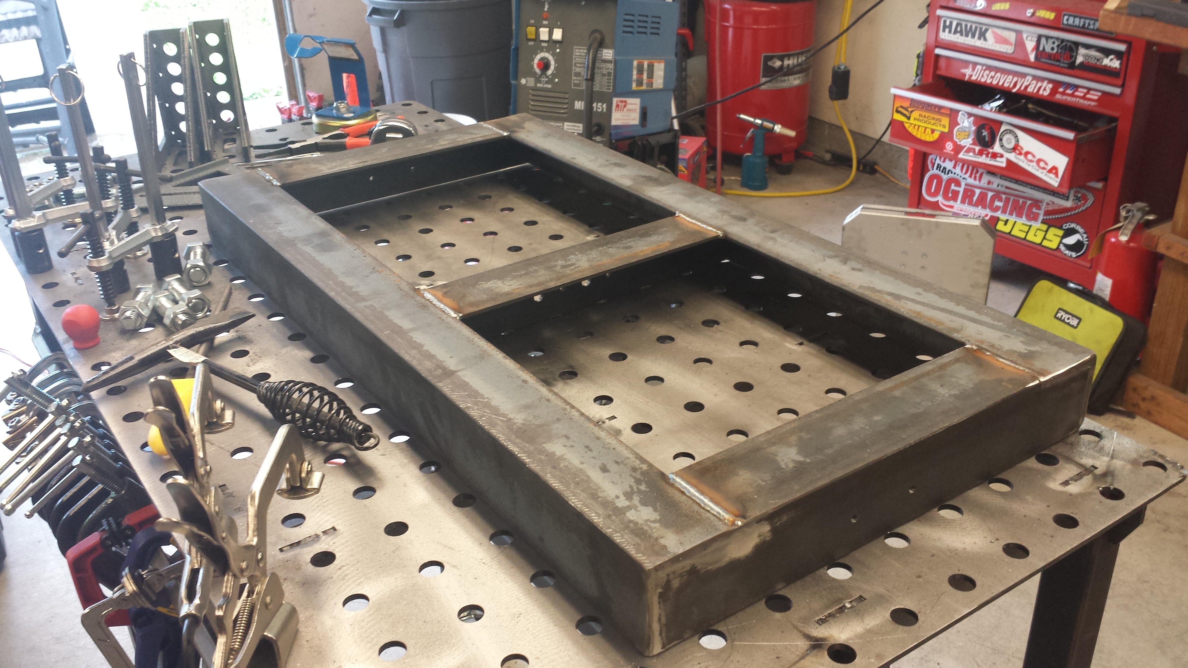
A quick test fit was very encouraging. My measuring a dozen times lead to a fit that allows the scale pads to rock in and out easily, but not enough that they can move around too much.
Mocking up the legs:
Got the rest of the gussets and the horizontal supports done.
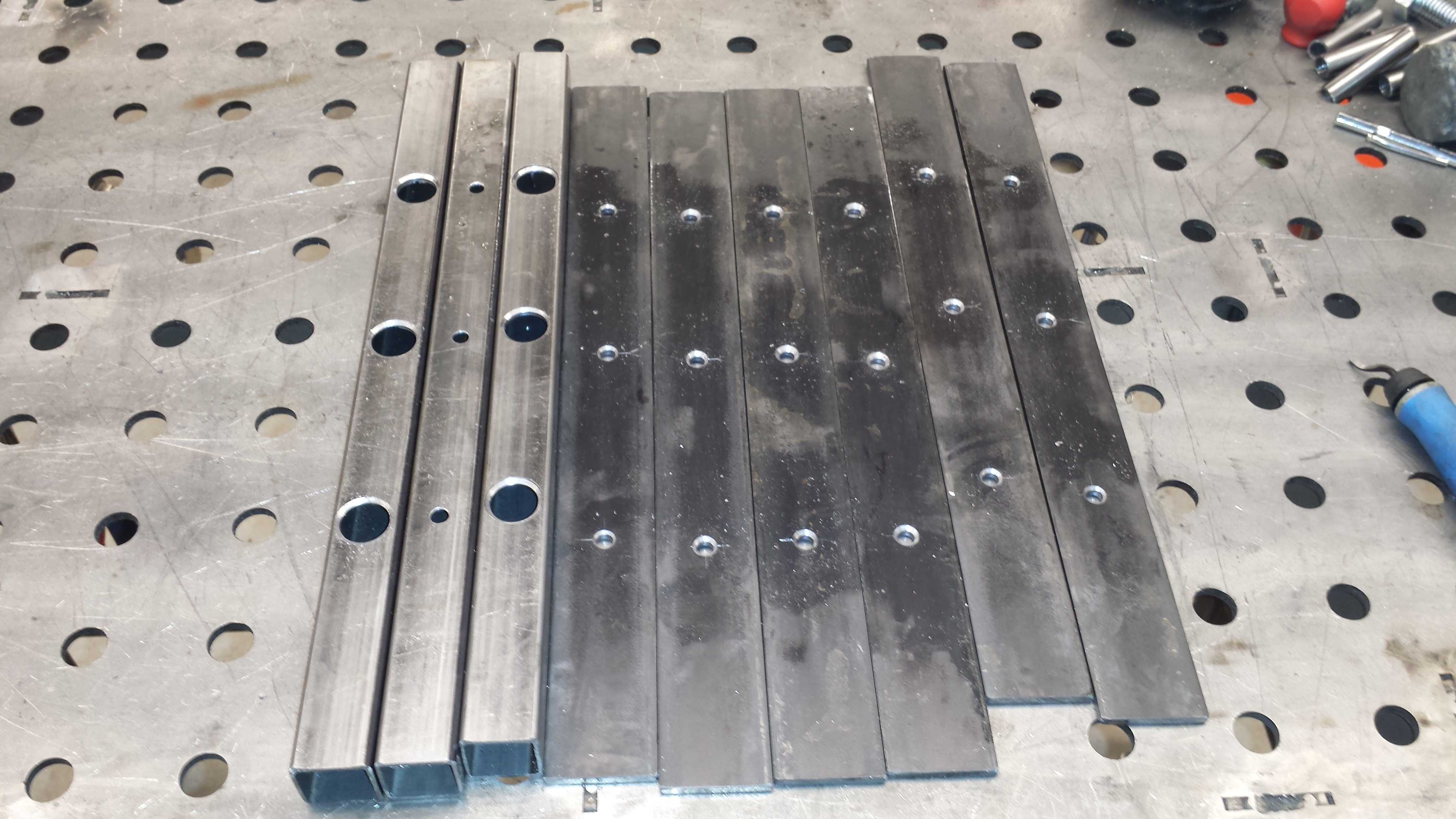
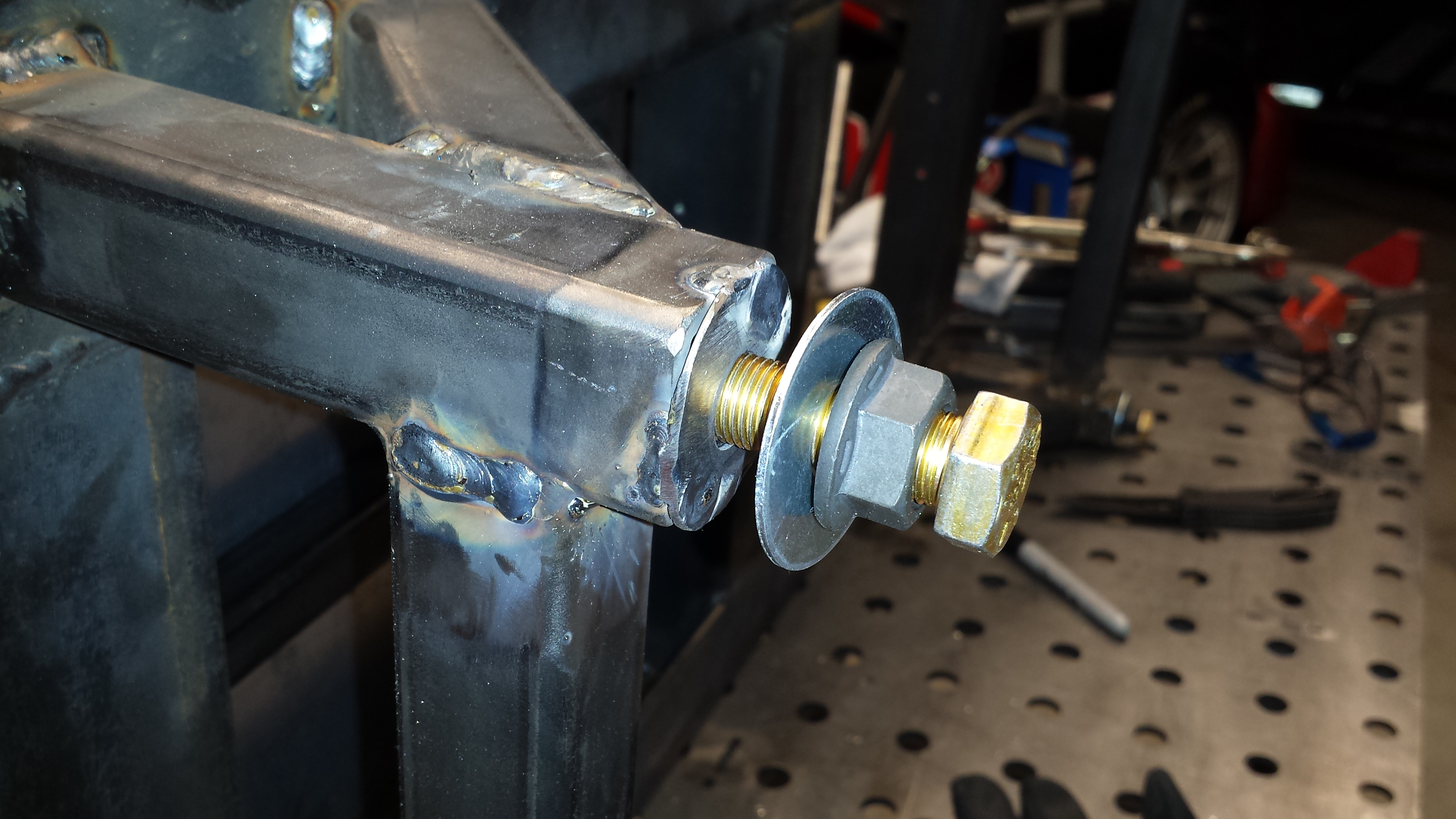
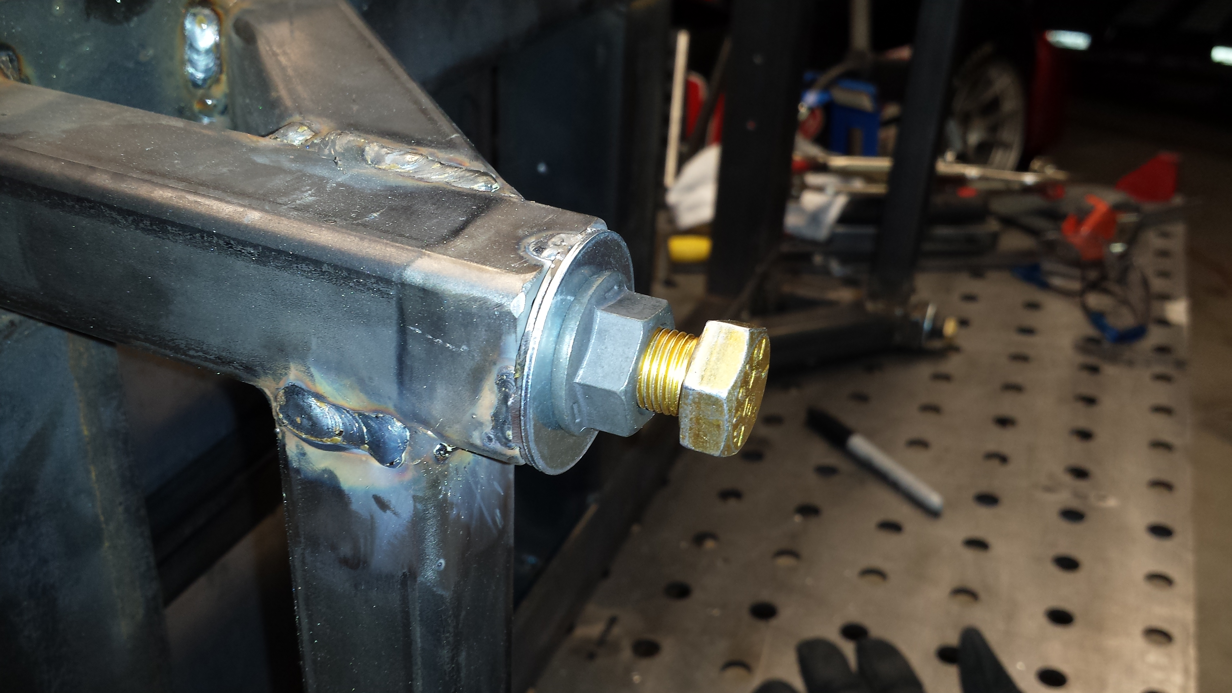
A design requirement was to have feet at each corner that will allow the full set to be leveled. The first step of that are these that make the bottom of the legs, with the threaded nut inside the leg. So, weld the nut to the washer, then weld that assembly to the leg.
The rest of the parts stackup.
This once again goes into the strength of the thing. Once the jam nut is tightened up, all of the load is on the big washers at the bottom of the legs and the bolt, and virtually none of the operating load is on the tack welds securing the nut on the inside of the legs.
With the basic design roughed out, we’ll work on the roll off pads in Part 2.